Linear actuator

Active Publication Date: 2021-03-04
CANON KK
View PDF5 Cites 2 Cited by
  • Summary
  • Abstract
  • Description
  • Claims
  • Application Information

AI Technical Summary

Benefits of technology

The present disclosure relates to a linear actuator with improved heat transfer capabilities. The actuator includes a guide rail, a wall portion, a coil, a heat transfer member, a heat radiation member, and a heat insulation member. The heat transfer member is located away from the wall portion, and the heat radiation member is installed on the actuator's end. This design helps to efficiently transfer heat away from the actuator, reducing its operating temperature. In summary, the technical effect of this patent is to provide a linear actuator with improved heat transfer capabilities, allowing for lower operating temperatures and better performance.

Problems solved by technology

Further, since the position of a position detector is shifted due to the thermal expansion of the frame, detection accuracy for the position of the mover is also reduced.
Furthermore, to increase heat insulation performance of the heat insulation member and heat transfer performance of the heat transfer member, a special material is required to be used, respectively, which increases the cost of the apparatus.
Thus, even when the structure in Japanese Patent Application Laid-Open No. 2018-78668 is employed to the linear actuator, it is difficult to completely prevent the heat generation of the coil unit from being transferred to the frame, and as a result, the frame is thermally expanded.
Thermal expansion of the frame contributes to a reduction in positioning accuracy of the mover.

Method used


Image

  • Linear actuator
  • Linear actuator
  • Linear actuator

Examples


Embodiment Construction

[0015]A processing system according to one embodiment of the present disclosure will be described with reference to FIG. 1 to FIG. 5. Note that, for a plurality of the same components in the descriptions and drawings described below, when a distinction is required, a lowercase alphabet is added at the end of the same numerical reference as an identifier, and when a distinction is not particularly required, the identifier is omitted and only the numerical reference is used.

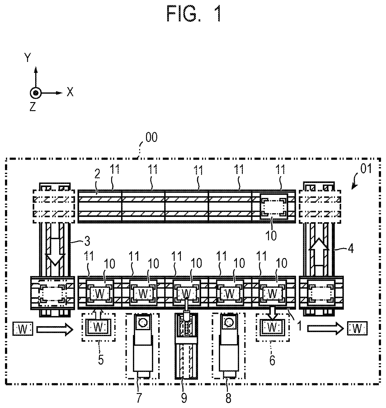
[0016]First, the overall configuration of the processing system according to the present embodiment will be described with reference to FIG. 1. FIG. 1 is a schematic diagram illustrating the overall configuration of the processing system according to the present embodiment and schematically illustrates the overall system when viewed from the top face.

[0017]A product having a complex shape and structure such as a camera and a printer cartridge is often assembled on a production line by continuous work. Adjacent asse...


PUM


Abstract

A linear actuator includes a guide rail, a wall portion, a coil, a heat transfer member, a heat radiation member, and a heat insulation member. A mover having a permanent magnet is movable along the guide rail. The wall portion is installed on a pedestal and supports the guide rail. The heat transfer member is coupled to the coil and the heat radiation member is coupled to an end of the heat transfer member. The heat insulation member is installed on the pedestal and coupled to the heat radiation member. The heat transfer member is arranged apart from the wall portion.

Description

BACKGROUNDField[0001]The present disclosure relates to a linear actuator.Description of the Related Art[0002]Japanese Patent Application Laid-Open No. H11-113238 discloses a movable magnet type linear actuator having a mover with a permanent magnet unit and a stator with an armature unit. In Japanese Patent Application Laid-Open No. H11-113238, since the armature units are arranged so as to hold the permanent magnet unit, suction force that works between an excitation core of the armature unit and a permanent magnet of the permanent magnet unit is cancelled. Thereby, it is possible to suppress deformation of the stator frame due to the suction force.[0003]In Japanese Patent Application Laid-Open No. H11-113238, however, an increase in speed and an increase in density of the mover causes an increase in the amount of heat generation of a coil, and the heat from the coil is transferred to the frame to which the coil is fixed. Since deflection is caused on the frame due to thermal expan...

Claims


Application Information

Patent Timeline
IPC IPC(8): H02K9/22H02K41/03B65G54/02
CPCH02K9/22B65G54/02H02K41/031H02K41/02H02K9/00
Inventor OKAZAKI, RYOTA
Owner CANON KK
Why Eureka
Try Eureka