Eureka AIR delivers breakthrough ideas for toughest innovation challenges, trusted by R&D personnel around the world.

Method of non-destructive imaging of the internal structure and device for carrying out the method

Pending Publication Date: 2021-03-11
RADALYTICA AS
View PDF4 Cites 4 Cited by
  • Summary
  • Abstract
  • Description
  • Claims
  • Application Information

AI Technical Summary

Benefits of technology

The invention is a method and device for inspecting the internal structure of an object without using penetrating energy, such as X-rays. The method involves scanning the surface of the object using a laser or other optical method to create a virtual image of the surface. The operator can then examine the object in a way that mimics looking at it with their own eyes. The device includes a source of radiation and a detector for detecting the radiation that has been influenced by the internal structure of the object. The device can be controlled remotely, making it easy to examine objects at large distances without the need for physical presence. The technical effects of the invention include the ability to inspect objects in a safe and non-destructive way.

Problems solved by technology

The disadvantages of this solution consist in the fact that this method of imaging is time-consuming because of the long delay between measurement and analysis, and therefore, the image cannot be immediately modified with respect to the findings, and because the change of position is often limited to only some of the directions: up and down, forward and backward, or sideways.
The disadvantages of the CT scanning involve the need for a large set of images to accurately develop the three-dimensional model of the internal structure.
The CT systems, both with a rotating pair of detector and X-ray tube, or the systems, which rotate the sample, do not allow inspection of the selected parts of larger units, for example, it is impossible to check the wing flap without dismantling it from the wing of aircraft.
Not all objects are in size and shape suitable for CT scanning.
The limitations of the current method of non-destructive imaging include hazards of radiation of the penetrating form of energy to human health, which requires the operator conducting such imaging to operate remotely, making it difficult to work due to limited manipulation of the object or the source of radiation source and the detector.
At the same time, the need for remote operation makes the real-time imaging difficult and unnatural task for the operator, especially in the spatial imaging because the standard procedure is to take a set of images and subsequently evaluate the images.
Last but not least, the limitation, especially in heterogeneous composite materials, is that some defects are visible only at a certain angle of imaging, which may not be included in the set of images.
On the other hand, disadvantages of this solution consist in the fact that the distance between the source of radiation and the detector is fixed so that taking images of the details of the internal structure is problematic.
At the same time, the combination of the detector and the source of radiation on a single beam considerably increases the weight and results in the need to use large industrial robots.
The disadvantages of such solution are similar to those of classical CT mainly based on the data processing.
The measured data is “off-line” analysed in the same way as in classical CT and the systems do not allow interactive check of the sample by operator.
With the current state of the art, it is therefore difficult to conduct inspection in a way natural for the operator as it is used in visual inspection.
At the same time, it is not simply possible to use the capabilities of the human brain, which is able to very quickly and efficiently evaluate information on the 3D structures of the object to be examined under the condition that the object can be rotated freely or viewed from different angles.

Method used


Image

  • Method of non-destructive imaging of the internal structure and device for carrying out the method

Examples


Embodiment Construction

[0040]It shall be understood that the specific cases of the invention embodiments described and depicted below are provided for illustration only and do not limit the invention to the examples provided here. Those skilled in the art will find or, based on routine experiment, will be able to provide a greater or lesser number of equivalents to the specific embodiments of the invention which are described here. Also such equivalents will be included in the scope of the following claims.

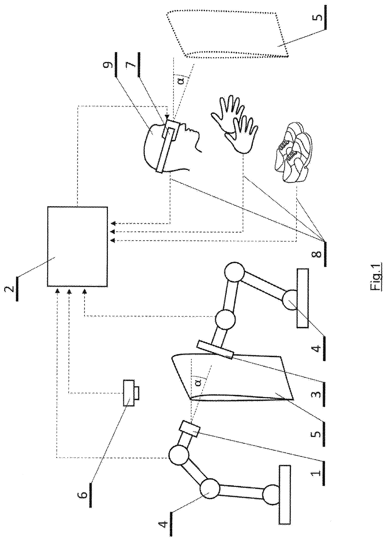
[0041]FIG. 1 shows the source of radiation 1 fixed to the robotic arm 4. In this particular embodiment of the invention, the source 1 of radiation may be the electrically powered X-ray tube, but in other examples of embodiment of the invention, the source 1 of radiation may be, for example, the radioactive isotope, ultrasound generator, etc. An expert in the field of forms of penetrating energy will be able to select other alternatives for the source 1 of radiation that can be used for imaging the inter...


PUM


Abstract

The invention relates to non-destructive imaging of the internal structure for safe and intuitive operator work. In the context of the invented method, electronic scanning first creates a virtual image of the surface of the object (5) whose internal structure is the subject of research. Part of the surface of the object (5) and the angle of scanning are set by voice or by movement of the operator's body (9). The virtual image of the surface of the object (5) is subsequently projected in the stereoscopic glasses (7), followed by creation of the virtual image of the internal structure of the object (5) for the same angle of scanning. The virtual image of the internal structure is projected in the virtual image of the surface of the object (5), or replaces the virtual image of the object (5).

Description

FIELD OF THE INVENTION[0001]The invention relates to real-time non-destructive imaging of the internal structure of at least part of the object using a virtual image.BACKGROUND OF THE INVENTION[0002]The internal structure of objects that are visually opaque is currently determined by means of radiation of the penetrating form of energy such as ultrasonic waves or ionizing radiation. This radiation penetrates through the internal structure impenetrable for visible light and if the radiation leaving the tested structure is detected, the image is obtained with information about the internal structure of the object.[0003]Radiographic imaging is known, in which the object to be imaged is placed between the source of ionizing radiation and the screen or image detector. In industry, to that end gamma rays or X-rays, which are used also in the area of medicine, are used. The advantage of radiography is non-destructive image of the structure of the object to be displayed.[0004]In the executi...

Claims


Application Information

Patent Timeline
IPC IPC(8): G01N23/044G01N23/046H04N13/344
CPCG01N23/044G01N2223/42H04N13/344G01N23/046G01N23/083G01N23/18G06T7/0004G01N2021/1776G01N2021/0162G01B11/24G01N23/02G06T19/006G01N29/0672G01N29/265G01N2223/1013G01N2223/106G01N2223/1016G01N29/0618G01N2223/3303
Inventor UHER, JOSEFZAHALKA, JAN
Owner RADALYTICA AS
Why Eureka
Eureka Blog
Learn More