Vehicle and method of controlling vehicle

a technology of vehicle and control device, which is applied in the direction of battery/fuel cell control arrangement, transportation and packaging, etc., can solve the problems of secondary battery not being charged, consuming the regenerative electric power of secondary, and all of a sudden consuming regenerative electric power, so as to prevent the noise of the driving auxiliaries

Active Publication Date: 2021-03-18
TOYOTA JIDOSHA KK
View PDF0 Cites 1 Cited by
  • Summary
  • Abstract
  • Description
  • Claims
  • Application Information

AI Technical Summary

Benefits of technology

[0007]According to the vehicle in this aspect of the disclosure, when the operational maneuver for making a change to the operation mode in which a larger amount of the regenerative electric power is generated is performed with the regenerative electric power generated, the auxiliary is caused to consume the regenerative electric power in accordance with the operational maneuver. Therefore, the increase in driving noise of the auxiliary for consuming the regenerative electric power is concomitant with the aforementioned operational maneuver performed by the user of the vehicle. As a result, the feeling of strangeness imparted to the user by the increase in driving noise of the auxiliary resulting from the consumption of the regenerative electric power can be reduced.
[0011]According to the vehicle in this aspect of the disclosure, the accuracy in estimating whether or not the electric storage device is in the non-chargeable state can be further enhanced.
[0013]According to the vehicle in this aspect of the disclosure, even when the first auxiliary generates a relatively loud driving noise in performing the specific maneuver control, the generation of this driving noise is concomitant with the operational maneuver for making a change to the operation mode in which a larger amount of the regenerative electric power is generated. Therefore, the user can be restrained from developing a feeling of strangeness. Besides, in the case where the second auxiliary as well as the first auxiliary is used to consume the regenerative electric power, even when the generation of driving noise of the second auxiliary is not concomitant with the aforementioned operational maneuver, the user can be restrained from developing a feeling of strangeness, because the driving noise of the second auxiliary is relatively quiet.
[0015]According to the vehicle in this aspect of the disclosure, when the second auxiliary alone cannot consume the regenerative electric power in performing the non-chargeable control, the first auxiliary as well as the second auxiliary is used to consume the regenerative electric power. Therefore, the driving noise of the auxiliaries resulting from the consumption of the regenerative electric power by the auxiliaries can be abated, and the user can be restrained from developing a feeling of strangeness.

Problems solved by technology

In some cases, however, the secondary battery cannot be charged, for example, when the remaining capacity (SOC) of the secondary battery is equal to or larger than a reference value.
In this case, conventionally, an air compressor or the like with which the fuel cell vehicle is mounted is caused to consume the regenerative electric power with which the secondary battery cannot be charged (e.g., see Japanese Unexamined Patent Application Publication No. 2013-218789 (JP 2013-218789 A)).
However, when the above-mentioned control is performed, an auxiliary, for example, the air compressor or the like may start consuming the regenerative electric power all of a sudden, independently of the intention of a user of the fuel cell vehicle.
As a result, the user of the fuel cell vehicle may develop a feeling of strangeness due to driving noise of the air compressor or the like.
Besides, a user of any vehicle that is configured to cause an auxiliary to consume a regenerative electric power with which a secondary battery cannot be charged as well as the fuel cell vehicle may develop a feeling of strangeness due to driving noise of the auxiliary generated at the time of the start of consumption of the regenerative electric power.
Therefore, the increase in driving noise of the auxiliary for consuming the regenerative electric power is concomitant with the aforementioned operational maneuver performed by the user of the vehicle.
According to the vehicle in this aspect of the disclosure, even when the first auxiliary generates a relatively loud driving noise in performing the specific maneuver control, the generation of this driving noise is concomitant with the operational maneuver for making a change to the operation mode in which a larger amount of the regenerative electric power is generated.

Method used


Image

  • Vehicle and method of controlling vehicle
  • Vehicle and method of controlling vehicle
  • Vehicle and method of controlling vehicle

Examples


first embodiment

A. First Embodiment

[0023](A-1) General Configuration of Fuel Cell Vehicle:

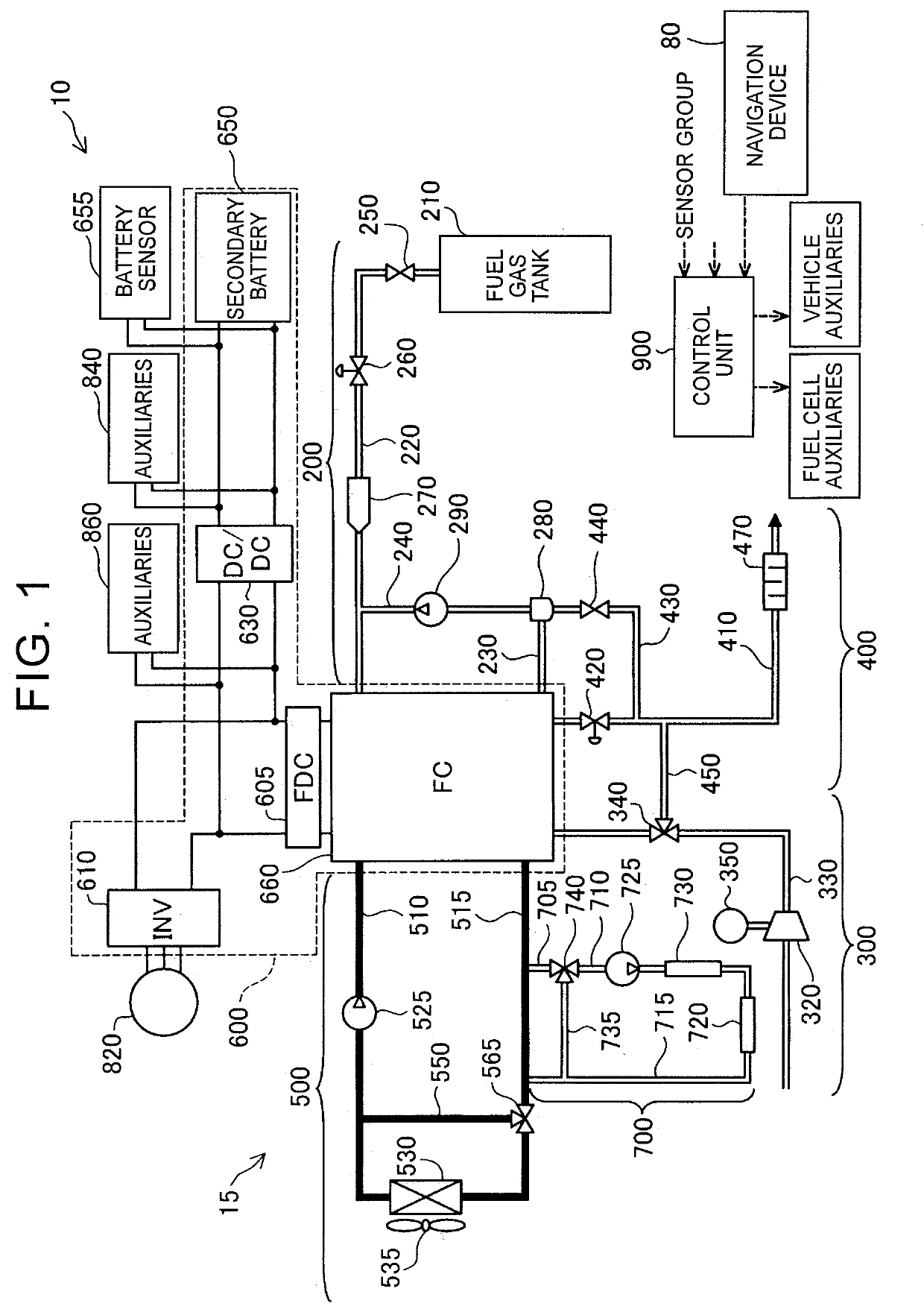
[0024]FIG. 1 is an illustrative view schematically showing the overall configuration of a fuel cell vehicle 10 as the first embodiment. The fuel cell vehicle 10 is equipped with a fuel cell system 15, an electric power circuit 600, a heating system 700, a drive motor 820, and a control unit 900. The fuel cell system 15 is equipped with a fuel cell 660, a fuel gas supply system 200, an oxidation gas supply system 300, an exhaust gas system 400, and a cooling system 500.

[0025]The fuel cell 660 has a stack configuration in which a plurality of single cells are laminated on one another, and generates electric power by being supplied with fuel gas containing hydrogen and oxidation gas containing oxygen. The fuel cell 660 according to the present embodiment is a polymer electrolyte fuel cell. In each of the single cells constituting the fuel cell 660, a flow channel (an anode-side flow channel) through which fuel ga...

second embodiment

B. Second Embodiment

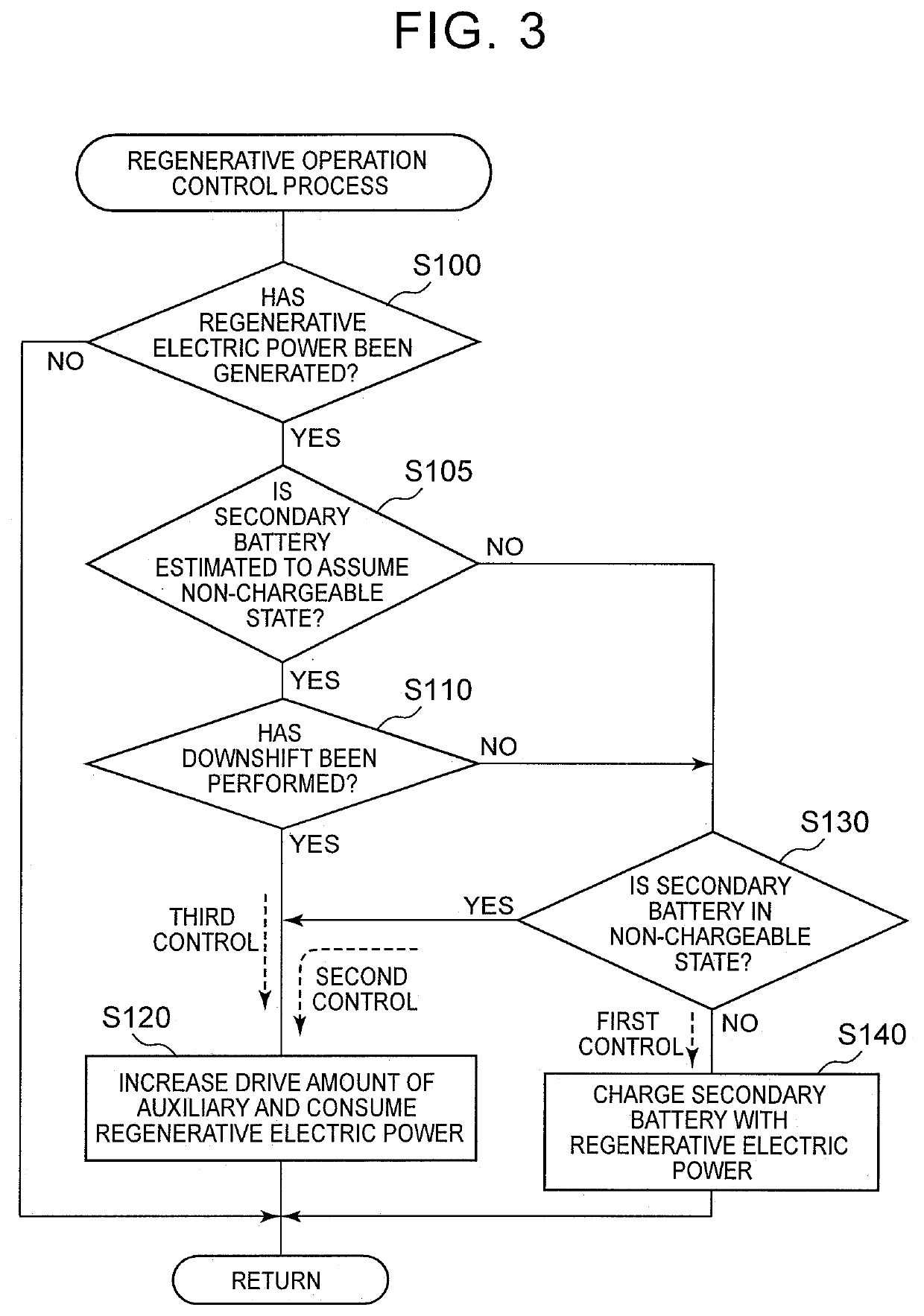
[0059]FIG. 3 is a flowchart representing a regenerative operation control process routine that is performed by the control unit 900 of the fuel cell vehicle 10 according to the second embodiment. The fuel cell vehicle 10 according to the second embodiment is similar in configuration to the fuel cell vehicle 10 according to the first embodiment, so detailed description thereof will be omitted. The flowchart of FIG. 3 and the flowchart of the first embodiment shown in FIG. 2 have something in common. Therefore, common steps are denoted by the same step numbers respectively, and detailed description thereof will be omitted.

[0060]In the fuel cell vehicle 10 according to the second embodiment as well as the first embodiment, the first control, the second control and the third control can be performed. The second embodiment is different from the first embodiment in that it is determined whether or not the secondary battery 650 is estimated to assume the non-chargeable ...

third embodiment

C. Third Embodiment

[0067]FIG. 4 is a flowchart representing a regenerative operation control process routine that is executed by the control unit 900 of the fuel cell vehicle 10 according to the third embodiment. The fuel cell vehicle 10 according to the third embodiment is similar in configuration to the fuel cell vehicle 10 according to the first embodiment, so detailed description thereof will be omitted. The flowchart of FIG. 4 and the flowchart of the first embodiment shown in FIG. 2 have something in common. Therefore, common steps are denoted by the same step numbers respectively, and detailed description thereof will be omitted.

[0068]The first control, the second control and the third control can be performed in the fuel cell vehicle 10 according to the third embodiment as well as the first embodiment. The third embodiment is different from the first embodiment in that the auxiliaries for use are prioritized when the second control and the third control are performed to caus...


PUM


Abstract

A vehicle is equipped with an electric storage device, a drive motor, an auxiliary that can be driven by a regenerative electric power, and a control unit. The control unit performs a non-chargeable control for causing the auxiliary to consume the regenerative electric power when the electric storage device is in a non-chargeable state, and performs a specific maneuver control for causing the auxiliary to consume the regenerative electric power even when the electric storage device is in a chargeable state in the case where an operational maneuver for making a change to an operation mode in which a larger amount of the regenerative electric power is generated is performed with the regenerative electric power generated.

Description

INCORPORATION BY REFERENCE[0001]The disclosure of Japanese Patent Application No. 2017-201649 filed on Oct. 18, 2017 including the specification, drawings and abstract is incorporated herein by reference in its entirety.BACKGROUND1. Technical Field[0002]The disclosure relates to a vehicle and a method of controlling the vehicle.2. Description of Related Art[0003]In a fuel cell vehicle which is mounted with a fuel cell, a regenerative electric power is generated in a drive motor of the vehicle at the time of deceleration or the like of the vehicle. This regenerative electric power is generally used to charge a secondary battery or the like with which the fuel cell is mounted, so the energy efficiency in the fuel cell vehicle is enhanced. In some cases, however, the secondary battery cannot be charged, for example, when the remaining capacity (SOC) of the secondary battery is equal to or larger than a reference value. In this case, conventionally, an air compressor or the like with wh...

Claims


Application Information

Patent Timeline
Patent Type & Authority Applications(United States)
IPC IPC(8): B60R16/033B60L1/00B60L7/10
CPCB60R16/033B60L1/08B60L7/10B60L1/003B60R16/02B60L1/00B60L2240/545B60L2240/547B60L58/32B60L50/75B60L50/70B60W30/18127H02J7/1446H02J2300/30Y02T10/92
Inventor KATO, SHOYUMITA, OSAMU
Owner TOYOTA JIDOSHA KK
Why Eureka
Try Eureka