Deburring device

Pending Publication Date: 2021-03-25
FANUC LTD
View PDF0 Cites 2 Cited by
  • Summary
  • Abstract
  • Description
  • Claims
  • Application Information

AI Technical Summary

Benefits of technology

The patent text discusses a technology for deburring machining on a three-dimensionally shaped ridge line using laser application. The technology aims to provide a stable gas flow for effective deburring. The text describes the importance of a stable gas flow for efficient deburring and proposes a solution to ensure that the gas flow is stable during the machining process. This technology can be useful in various industries where efficient deburring is required.

Problems solved by technology

However, deburring machining is machining on a three-dimensionally shaped ridge line, and the flow of an assist gas in the vicinity of a machining point is complicated.
A target of deburring machining often includes, in the position of a ridge line, the angle of a plane forming the ridge line and the like, a large number of errors from a geometric shape in design.

Method used


Image

  • Deburring device
  • Deburring device
  • Deburring device

Examples


first embodiment

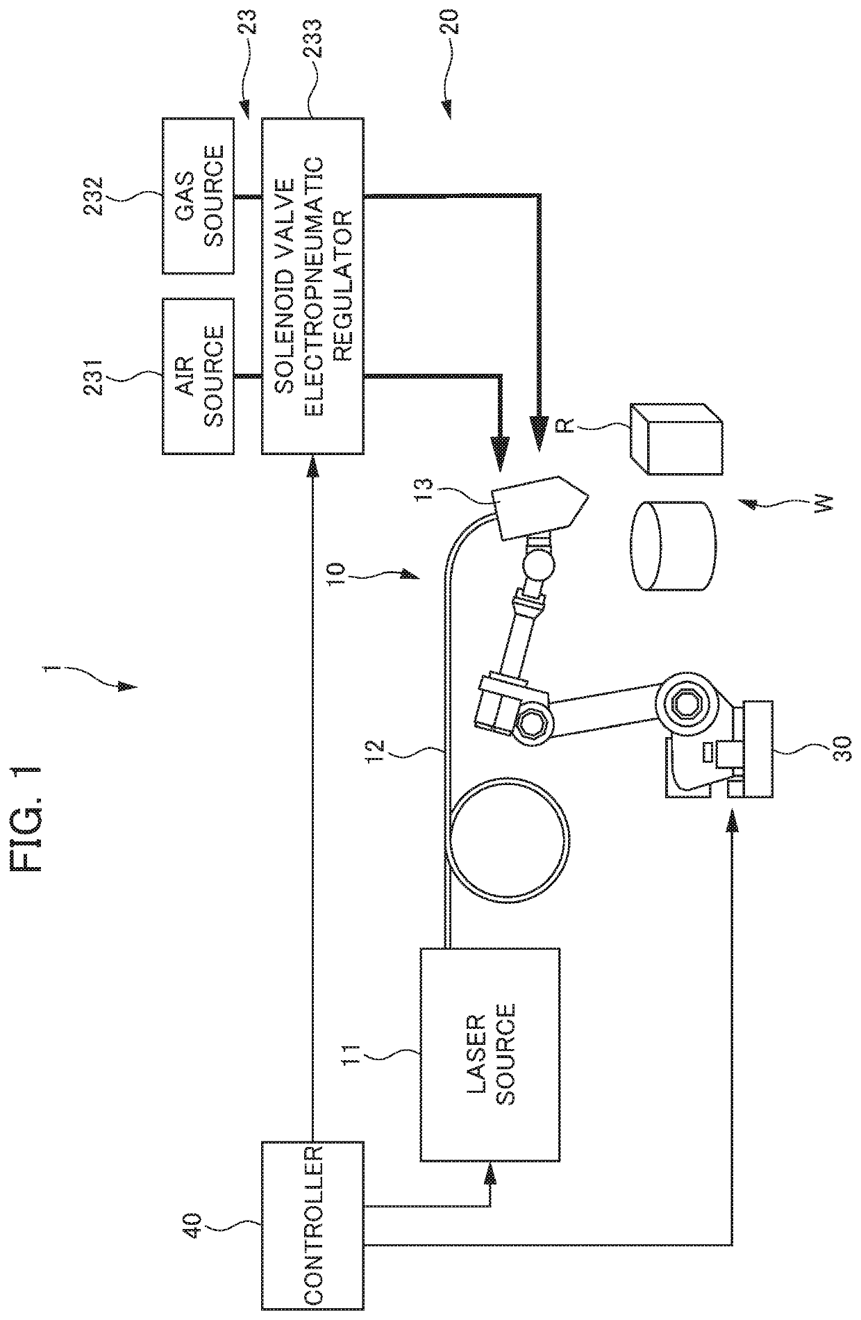
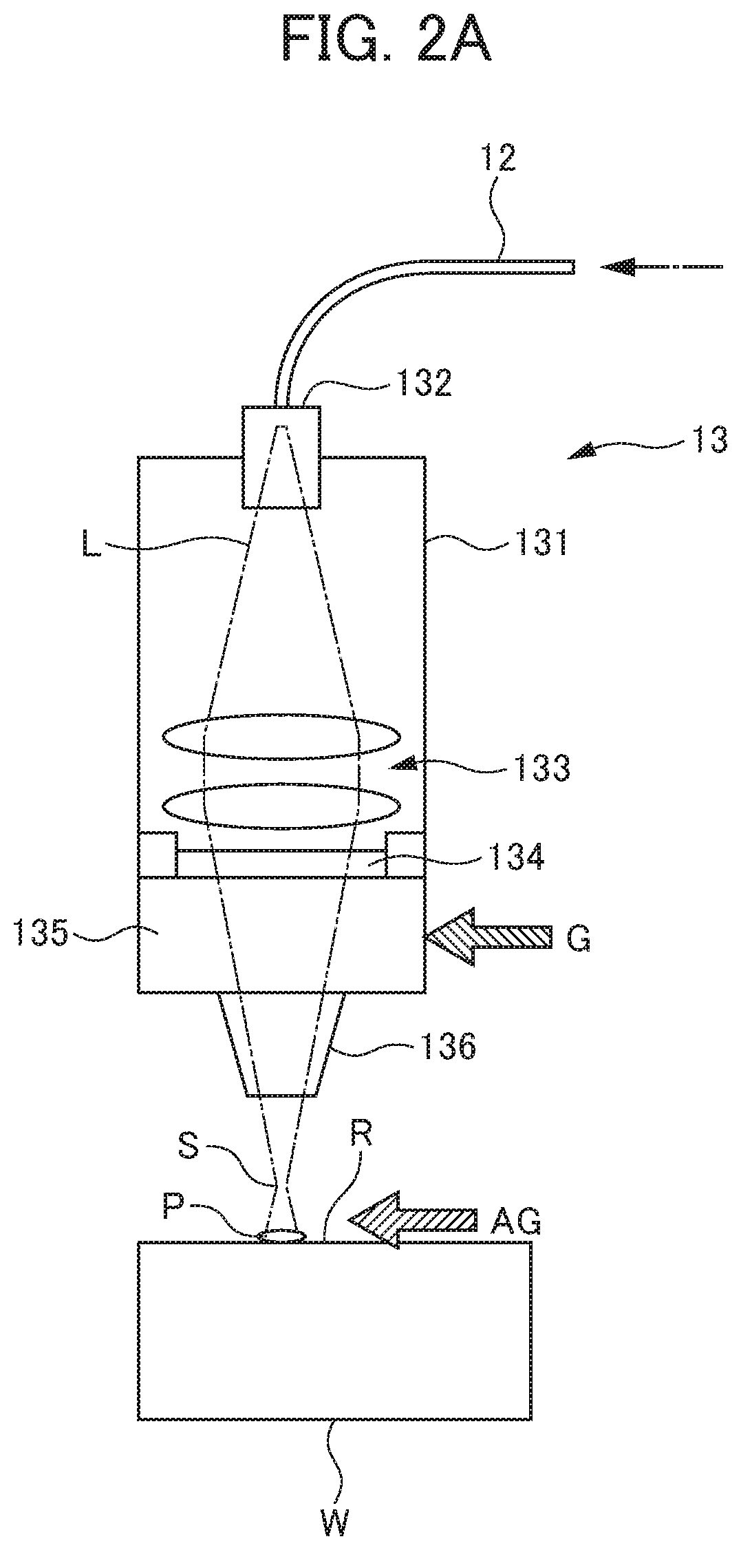
[0025]FIG. 1 is a diagram showing the configuration of a deburring device 1 according to the first embodiment. The deburring device 1 according to the present embodiment is a device for removing burrs which are present on a ridge line R of a workpiece W (three-dimensional shape) after being machined. As shown in FIG. 1, the deburring device 1 according to the present embodiment includes a laser device 10, a gas jetting device 20, a transport device 30 and a controller 40.

[0026]The workpiece W is a workpiece which has been machined and molded by cutting, turning, forging, casting, laser cutting, pressing, powder sintering or the like. The workpiece W is typically a workpiece in which an unintended surplus material (burr) is present on the ridge line R of a boundary between surfaces in a three-dimensional shape due to uncut portions or the like. The material of the workpiece W is not limited, and a workpiece formed of a metal, a resin, an inorganic material or another material can be ...

second embodiment

[0058]A deburring device according to the second embodiment has the same configuration as the deburring device according to the first embodiment except that the deburring device according to the second embodiment includes a pair of gas jetting nozzles and a pair of angle adjustment arms and that the arrangement of the pair of gas jetting nozzles is different from the first embodiment. FIG. 7 is a plan view showing the configuration of a gas getting device 20A in the deburring device according to the present embodiment. FIG. 8 is a side view showing the configuration of the gas jetting device 20A in the deburring device according to the present embodiment. FIGS. 9 and 10 are front views (diagrams when the machining point a is seen from the forward side in the scanning direction) showing laser application using the deburring device according to the present embodiment, FIG. 9 shows a case where the geometric relationship of the workpiece W with the laser light L and the gas jetting noz...

example 1

[0072]The deburring device 1 according to the first embodiment was used, and thus deburring machining was performed on the ridge line of a workpiece. Specifically, a fiber laser having a wavelength of 1070 nm was utilized, and as the workpiece, carbon steel S50C on which milling had been performed was used. The maximum height of burrs in the carbon steel S50C was 0.5 mm.

[0073]On the carbon steel S50C, the deburring machining was performed under conditions in which the diameter of a laser emitting end fiber core was 50 μm, in which an optical magnification was 1.5 times, in which a distance from a spot to a machining point was 23.2 mm, which the diameter of a beam at the machining point was about 1000 μm, in which a laser output was 230 W, in which a scanning speed was 300 mm / minute, in which the diameter of a gas jetting nozzle for an assist gas was φ6 mm, which a flow rate was 50 L / minute, in which a distance between a member of the gas jetting nozzle for the assist gas and the rid...


PUM

PropertyMeasurementUnit
Angleaaaaaaaaaa
Angleaaaaaaaaaa
Angleaaaaaaaaaa

Abstract

An object is to provide a technology in which in debarring machining on a three-dimensionally shaped ridge line by laser application, a stable gas flow can be supplied and in which stable deburring machining can be performed. A deburring device for removing a burr which is present on a ridge line of a workpiece after being machined, includes: a laser device which includes a laser machining head that applies laser light to the ridge line; a transport device which transports the laser device and a gas jetting, device; and a controller which controls the laser device, the gas jetting device and the transport device and the controller controls the gas jetting device and the transport device such that a gas jetting nozzle is moved on a plane including the bisector of an apex angle of the ridge line and the ridge line and that in a side view parallel to the ridge line, an angle formed by the ridge line and the central axis line of the gas jetting, nozzle is an acute angle.

Description

[0001]This application is based on and claims the benefit of priority from Japanese Patent Application No. 2019-173745, filed on 25 Sep. 2019, the content of which incorporated herein by reference.BACKGROUND OF THE INVENTIONField of the Invention[0002]The present invention relates to deburring devices.Related Art[0003]Conventionally, when cutting or the like is performed on a workpiece such as a metal, burrs are produced on a three-dimensionally shaped ridge line. This is also true for a case where a workpiece is a nonmetal and a case where a machining method is machining using a mold of casting, forging, powder sintering or the like or is another type of machining of pressing, laser or the like.[0004]Since burrs cause various problems in a post-process, it is necessary to remove them. Hence, various proposals for removing burrs with laser are made (see, for example, Patent Documents 1 to 3).[0005]When laser light is applied to burrs left on a three-dimensionally shaped ridge line s...

Claims


Application Information

Patent Timeline
IPC IPC(8): B23K26/361
CPCB23K26/361B23K26/0648B23K26/064B23K26/60B23K26/702B23K26/14B23K26/142B23K26/0652B23K26/0643B23K26/0884B23K26/147B23K26/1476B23K2103/04B23K26/0876B23K26/0869
Inventor MORI, ATSUSHI
Owner FANUC LTD
Why Eureka
Try Eureka