
Eureka
For R&D, Eureka makes reading and utilizing patents & technical documents easy.
Eureka AIR
Designed for self-driven R&D workflows. Generate viable solutions, solve complex R&D challenges, empower your innovation with AI.

Eureka Materials
Designed for material experts only. Revolutionize your material R&D, from search, analyze, to developing new materials.

TechResearch
Generate reliable direction feasibility study reports for your R&D in just a few steps.

TechSeek
Discover and master advanced knowledge NOW. Basics, ideas, possibilities, all at once.

TechMind
As an expert in R&D Theories, TechMind can generates customized viable solutions instantly.

TechRisk
Analyze your overall solution with one click, know your potential R&D risks in advance.

TechMonitor
Get weekly tech updates, stay abreast of the latest tech innovations and key insights.
Transdural electrode device for stimulation of the spinal cord
a transdural electrode and spinal cord technology, applied in the field of medical devices, can solve the problems of spinal cord injury, inadequate treatment, lost work and disability, etc., and achieve the effect of stabilizing the implan
- Summary
- Abstract
- Description
- Claims
- Application Information
AI Technical Summary
Benefits of technology
Problems solved by technology
Method used
Image

Examples
example 1
f Various Gaskets for Use with Intradural Stimulator
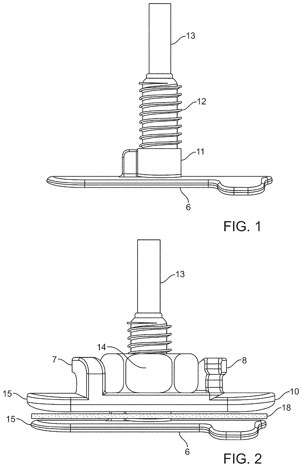
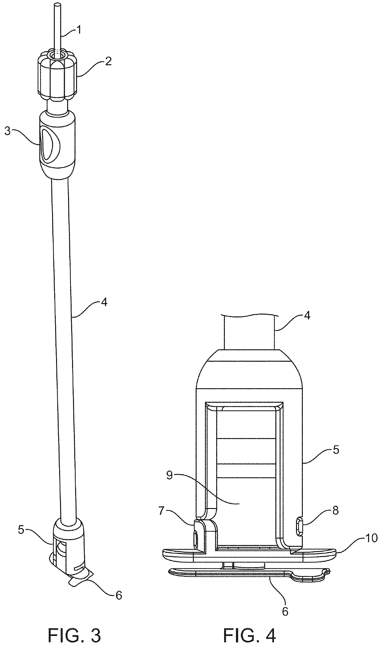
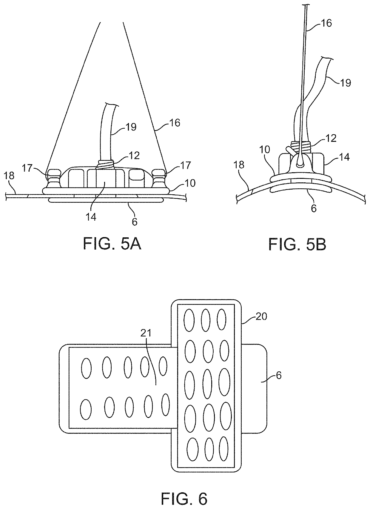
[0202]To test the workability of the gaskets as seal mechanisms against leakage of CSF, the compression plates and housing of the prototype intradural stimulator of the type shown in FIGS. 1 through 4 were implanted into a mock durotomy slot that had been cut into a Plexiglas® tube which simulated the thecal sac. A thin, smooth strip of polyethylene was used as the surrogate dura mater to insure that any leakage pathways would be associated only with the gaskets and not with porosity of the dural surrogate. The gaskets between the compression plates were made of Durepair®, which is a dura substitute often used to close and seal durotomies. The gasket thickness was nominally 0.5 mm, and of oval shape with length and width matching the dimensions of those of the intradural plate as shown in FIG. 10.
[0203]A syringe was connected to one end of the Plexiglas® tube and the other end was blocked shut. The tube was filled with water, with ...
example 2
of T Shaped Electrode and Selective Fiber Stimulation
[0205]The modeling described herein indicates that the intradural stimulation device can be used effectively to modulate targeted neural elements selectively within the spinal cord, while at the same time sparing non-targeted structures. Moreover, modeling, such as described in this Example 2, can be used to determine additional configurations of the intradural stimulation electrode array that can be used to selectively stimulate neural structures, such as for example, large fibers, small fibers, medium fibers and combinations thereof. At the most elementary level this means controlling or steering the electrical fields generated by the currents delivered from the electrode contacts; this usually involves both spatial and temporal control attributes. The spatial distribution of the field strength and gradient determines which neural elements are affected. Current flow through the axons passing into these fields may be susceptible ...
PUM
 Abstract
Description
Claims
Application Information
 - R&D Engineer
- R&D Manager
- IP Professional
- Industry Leading Data Capabilities
- Powerful AI technology
- Patent DNA Extraction
Browse by: Latest US Patents, China's latest patents, Technical Efficacy Thesaurus, Application Domain, Technology Topic, Popular Technical Reports.
© 2024 PatSnap. All rights reserved.Legal|Privacy policy|Modern Slavery Act Transparency Statement|Sitemap|About US| Contact US: help@patsnap.com