Cell culture apparatus and cell culture method

Pending Publication Date: 2021-04-08
FUJIFILM CORP
View PDF0 Cites 0 Cited by
  • Summary
  • Abstract
  • Description
  • Claims
  • Application Information

AI Technical Summary

Benefits of technology

[0006]The disclosed technique has been made in view of the above points, and an object thereof is to improve a tempera

Problems solved by technology

In a case where the temperature rising rate of the cell suspension in this case is low, the cells are exposed to a low temperature for a long time, which may adversely affect growing property and viability of the cells.
Moreover, in a general incubator, an atmospheric temperature inside the incubator is likely to be uneven due to the influence of a position of a heat source, a disposition of a blower fan, a direction of an air blow, a position of a heat insulating material insi

Method used


Image

  • Cell culture apparatus and cell culture method
  • Cell culture apparatus and cell culture method
  • Cell culture apparatus and cell culture method

Examples


Example

First Embodiment

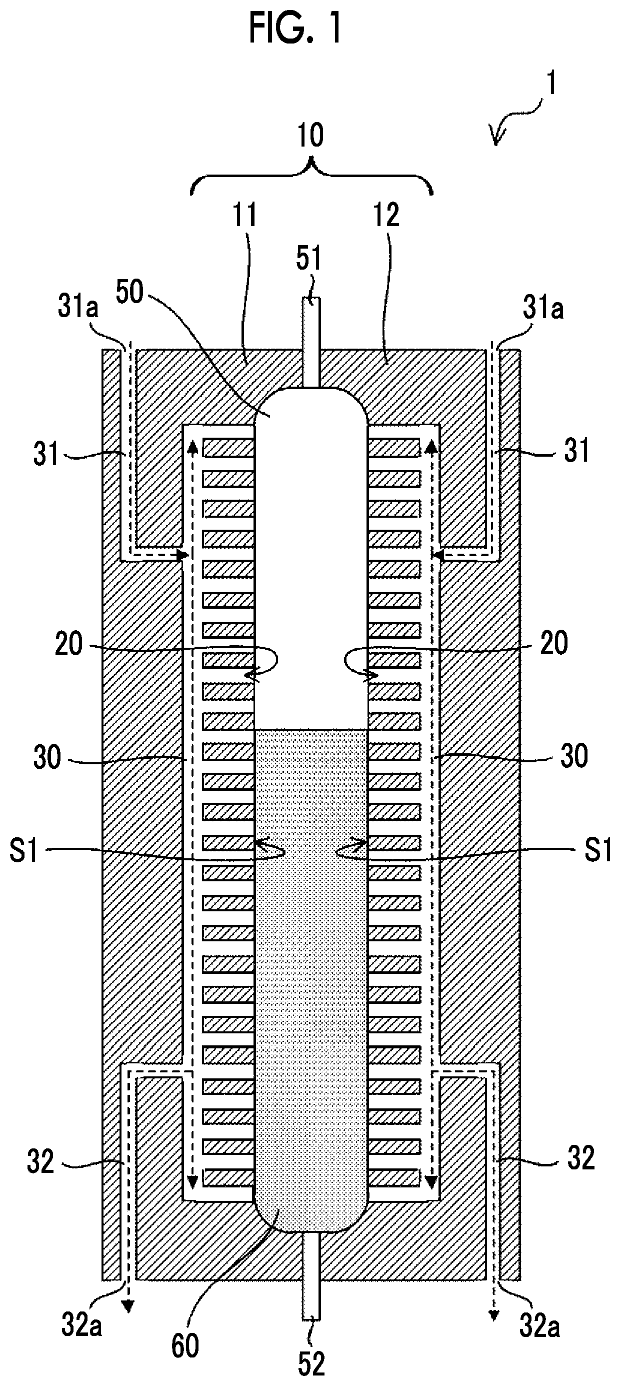
[0020]FIG. 1 is a cross-sectional view showing an example of a configuration of a cell culture apparatus 1 according to a first embodiment of the disclosed technique. FIG. 1 shows a culture vessel 50 for containing a cell suspension 60 containing cells to be cultured using the cell culture apparatus 1 and a medium, together with the cell culture apparatus 1. The culture vessel 50 has a bag shape configured to include a film which is gas-permeable. At one end part of the culture vessel 50, a gas flow port 51 is provided for allowing a gas for adjusting pressure inside the culture vessel 50 to flow into the culture vessel 50 or out of the culture vessel 50. At the other end part of the culture vessel 50, a liquid flow port 52 is provided for allowing the cell suspension 60 to flow into the culture vessel 50 or out of the culture vessel 50.

[0021]The cell culture apparatus 1 includes a heat transfer medium 10 that is in contact with a surface of the culture vessel 50. Th...

Example

Second Embodiment

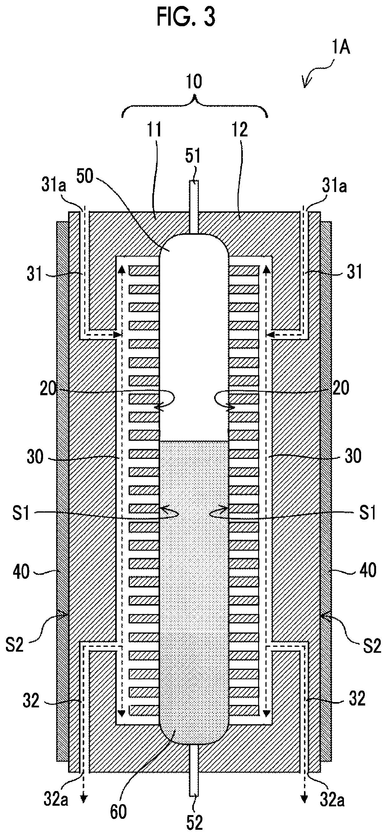
[0037]FIG. 3 is a cross-sectional view showing an example of a configuration of a cell culture apparatus 1A according to a second embodiment of the disclosed technique. The cell culture apparatus 1A includes a heater 40 attached to the heat transfer medium 10. The heater 40 is provided on each of back surfaces S2 opposite to the contact surfaces S1 respectively of the first part 11 and the second part 12 of the heat transfer medium 10 with the culture vessel 50.

[0038]The heater 40 is adjusted to a temperature (for example, 37° C.) suitable for promoting the growth of cells contained in the culture vessel 50. The heat generated from the heater 40 is conducted to the cell suspension 60 contained in the culture vessel 50 via the heat transfer medium 10, and the temperature of the cell suspension 60 rises to a desired temperature. It is noted that, in order to heat the heat transfer medium 10, a temperature-adjusted gas may be introduced into the heat transfer medium 10...

Example

Third Embodiment

[0040]FIG. 4 is a cross-sectional view showing an example of a configuration of a cell culture apparatus 1B according to a third embodiment of the disclosed technique.

[0041]Each of the first part 11 and the second part 12 of the heat transfer medium 10 has a recess part 21 and a protrusion part 22 on the contact surface S1 in contact with the culture vessel 50. FIGS. 5A and 5B are perspective views showing an example of a structure of the contact surface S1 of the heat transfer medium 10, respectively. On the contact surface S1 of the heat transfer medium 10, a plurality of the protrusion parts 22 are uniformly provided over the entire contact surface S1. A shape of the plurality of protrusion parts 22 is not particularly limited, and may be, for example, a rectangular parallelepiped as shown in FIG. 5A or a columnar shape as shown in FIG. 5B. The recess part 21 is formed in the gap between the plurality of protrusion parts 22, and respective portions of the recess p...


PUM


Abstract

Provided are a cell culture apparatus and a cell culture method which are capable of improving a temperature rising rate of a temperature rising target and enhancing a temperature uniformity of the temperature rising target. The cell culture apparatus includes: a heat transfer medium having a recess part or a plurality of hole parts in a contact surface with a culture vessel for containing a cell suspension; and an air supply port which communicates with the recess part or each of the plurality of hole parts and to which a gas is supplied.

Description

CROSS-REFERENCE TO RELATED APPLICATIONS[0001]This application is a continuation application of International Application No. PCT / JP2019 / 022762 filed Jun. 7, 2019 the disclosure of which is incorporated herein by reference in its entirety. Further, this application claims priorities from Japanese Patent Application No. 2018-133203, filed Jul. 13, 2018, the disclosure of which is incorporated herein by reference in its entirety.TECHNICAL FIELD[0002]The technique disclosed relates to a cell culture apparatus and a cell culture method.RELATED ART[0003]The following techniques are known as techniques relating to a cell culture apparatus. For example, JP2015-503361A describes a heat exchange module used in a chemical, pharmaceutical or biological reactor system. The heat exchange module is configured to be disposed in a reactor system having a flexible single-use container and includes at least one heat conductive surface that is made in contact with the flexible single-use container to p...

Claims


Application Information

Patent Timeline
IPC IPC(8): C12M1/02C12M1/04
CPCC12M41/20C12M23/24C12M41/22
Inventor INADA, ATSUSHIKATOU, NOBUHIKOTAKAYAMA, HIDETOSHI
Owner FUJIFILM CORP
Why Eureka
Try Eureka