
Flexible Shaft Structure Insulating Wear Particles by Perfusion

a flexible transmission shaft and wear particle technology, applied in the field of torque transmission structure can solve the problems that the prior art cannot be directly fails to meet the specification limit of sterile packaging of medical devices, and cannot be applied in the field of interventional medical devices, so as to ensure the stability of distal perfusion, ensure the reliability of distal perfusion sealing and the controllability of actual perfusion flow, and reduce noise and vibration

Pending Publication Date: 2021-04-22
FENGKAI MEDICAL INSTR (SHANGHAI) CO LTD
View PDF1 Cites 0 Cited by
  • Summary
  • Abstract
  • Description
  • Claims
  • Application Information

AI Technical Summary

Benefits of technology

The present invention solves the technical problem of wear particles generated during medical procedures by providing a flexible shaft structure that can supply cooling / lubricating liquid to a flexible transmission shaft and effectively insulate wear particles. This prevents the particles from entering a patient body and improves the stability and consistency of the perfusion flow of the product, while reducing vibration and noise of the flexible shaft under high-speed rotation. Compared to the prior art, the present invention has the advantage of supplying cooling or lubricating fluid, complete insulation of particles, ensuring stability of distal perfusion, reliability of distal perfusion sealing, and controllability of actual perfusion flow, as well as reduced noise and vibration of the flexible transmission shaft under high-speed rotation.

Problems solved by technology

Moreover, in the application of interventional instruments, insulation of wear particles is a unique technical challenge in the clinical application, and perfusion flushing is a common approach of improvement to wear control.
However, the improvement solutions in the prior art cannot be directly applied in the field of interventional medical devices.
On one hand, mature technical solutions in the industrial field require a large transmission structure with an outer diameter at least not smaller than 10 mm, so the prior art cannot be applied to interventional medical devices.
On the other hand, the mature technical solutions now available focus more on the transmission torque, with the supportable minimum bending radius being often relatively large and the bendable degree being generally smaller than 90°, and thus fail to satisfy the specification limit of sterile packaging of medical devices and the use context featuring complex bent channels in an interventional operation.
However, according to the technical solution, collaboration of two perfusion pumps and a plurality of sensors is necessary to realize precise flow control, complexities in the structure and the control algorithm lead to difficulties in implementation and high costs.
Furthermore, the technical solution, which in essence adopts still flushing removal, consumes extra perfusate.
Unlike the industrial environment where only cooling water is required, the medical perfusate has special composition and sterile requirements, so the extra consumption of the perfusate also means extra costs of consumables.

Method used


Image

  • Flexible Shaft Structure Insulating Wear Particles by Perfusion
  • Flexible Shaft Structure Insulating Wear Particles by Perfusion

Examples


Embodiment Construction

[0030]The present invention will now be further described with reference to the drawings and examples.

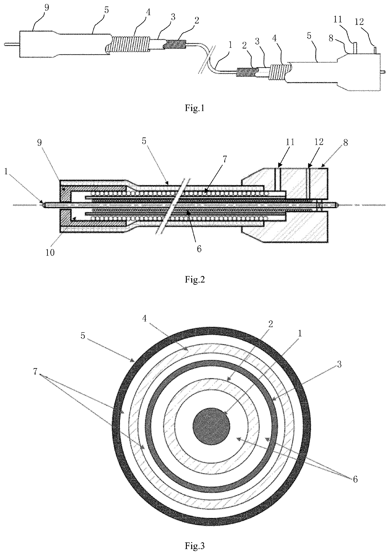
[0031]FIG. 1 is a schematic view showing a structure of a flexible shaft in an embodiment of the present invention; FIG. 2 is a schematic view showing an axial sectional structure of the flexible shaft along a flexible transmission shaft in an embodiment of the present invention; FIG. 3 is a schematic view showing a radial enlarged sectional structure of the flexible shaft along the flexible transmission shaft in an embodiment of the present invention.

[0032]Referring to FIGS. 1, 2 and 3, the present invention provides a flexible shaft structure insulating wear particles by perfusion, including a flexible drive shaft 1, a restraint insulator, an outer sheath tube 5, a distal holder 9 and a proximal holder 8.

[0033]The flexible drive shaft 1 is connected at its distal end with a rotating element of a blood pump intended to be used and at its proximal end to a driving power means intend...


PUM

PropertyMeasurementUnit
outer diameteraaaaaaaaaa
flexibleaaaaaaaaaa
weightsaaaaaaaaaa

Abstract

The present invention discloses a flexible shaft structure insulating wear particles by perfusion, which includes a flexible transmission shaft, a proximal holder is provided at one end of the flexible transmission shaft, a distal holder is provided at the other end of the flexible transmission shaft, a constraint insulator and an outer sheath tube are provided outside the flexible transmission shaft, and the constraint insulator sequentially includes an inner constraint layer, an insulation layer and an outer constraint layer from inside to outside; a perfusion inflow annular cavity is formed between the outer constraint layer and the outer sheath tube and between the outer constraint layer and the insulation layer, respectively, and a static sealed inner cavity is formed between the inner constraint layer and the insulation layer and between the inner constraint layer and the flexible transmission shaft, respectively; the proximal holder is provided with a perfusion inlet pipeline communicated with the perfusion inflow annular cavity and a perfusion exhaust pipeline communicated with the static sealed inner cavity; and the distal holder is provided with a perfusion insulation cavity. According to the present invention, the generated wear particles can be effectively insulated, the stability and consistency of perfusion flow of the product are improved, and the problems of vibration and noise of the flexible shaft under high-speed rotation are solved.

Description

TECHNICAL FIELD[0001]The present invention relates to a torque transmission structure in an interventional blood pumping catheter device for realizing an external power source, more particularly, to a flexible shaft structure insulating wear particles by perfusion.BACKGROUND ART[0002]Flexible shaft drive structures are widely used in different fields, but usually provide quite different main features in different fields. For example, large flexible shaft structures applied in the field of machine tools and fans may operate at lower rotating speeds but have to transmit higher torques; micro flexible shaft structures known in the dental field have to operate at very high speeds but only to transmit lower torques; those in the field of interventional instruments, such as intravascular ultrasound catheters, require compliance with complex twisting structures, but have only to transmit lower speeds and torques. Vibration and wear are common challenges in the use of flexible shafts, espec...

Claims


Application Information

Patent Timeline
Patent Type & Authority Applications(United States)
IPC IPC(8): A61M1/10F16C1/24
CPCA61M1/1046F16C1/24A61M1/1008A61M2205/366A61M2205/3606A61M2205/42A61M2205/3633F16C1/06F16C2316/10F16C1/267A61M60/13A61M60/205A61M60/408A61M60/414A61M25/0045A61M60/405A61M60/857
Inventor ZHENG, QIWENTANG, ZHIRONG
Owner FENGKAI MEDICAL INSTR (SHANGHAI) CO LTD
Learn More