Ultrasonic additively manufactured coldplates on heat spreaders

Active Publication Date: 2021-05-06
RAYTHEON CO
View PDF0 Cites 1 Cited by
  • Summary
  • Abstract
  • Description
  • Claims
  • Application Information

AI Technical Summary

Benefits of technology

[0004]Ultrasonic additive manufacturing (UAM) is advantageous in forming a cooling or manifold structure for a heat-dissipating surface, such as in an integrated circuit for high-power electronics. Using UAM to directly bond a coldplate to a heat spreader layer that is arranged adjacent the heat-dissipating surface is advantageous in e

Problems solved by technology

In contrast, the materials available for UAM are not s

Method used


Image

  • Ultrasonic additively manufactured coldplates on heat spreaders
  • Ultrasonic additively manufactured coldplates on heat spreaders
  • Ultrasonic additively manufactured coldplates on heat spreaders

Examples


Example

[0042]The principles described herein have particular application in a cooling structure or manifold used for cooling a heat-dissipating surface to which the cooling structure is attached. A cooling structure may include a heat spreader layer and a coldplate. Various applications may implement a cooling structure such as high-power electronics having integrated circuits or chips that dissipate a high heat flux. High power electronics and the corresponding cooling structure for the electronics may be used in aerospace applications, military applications, and commercial wireless, high-power amplifier applications. The cooling structure described herein may be implemented in many other applications.

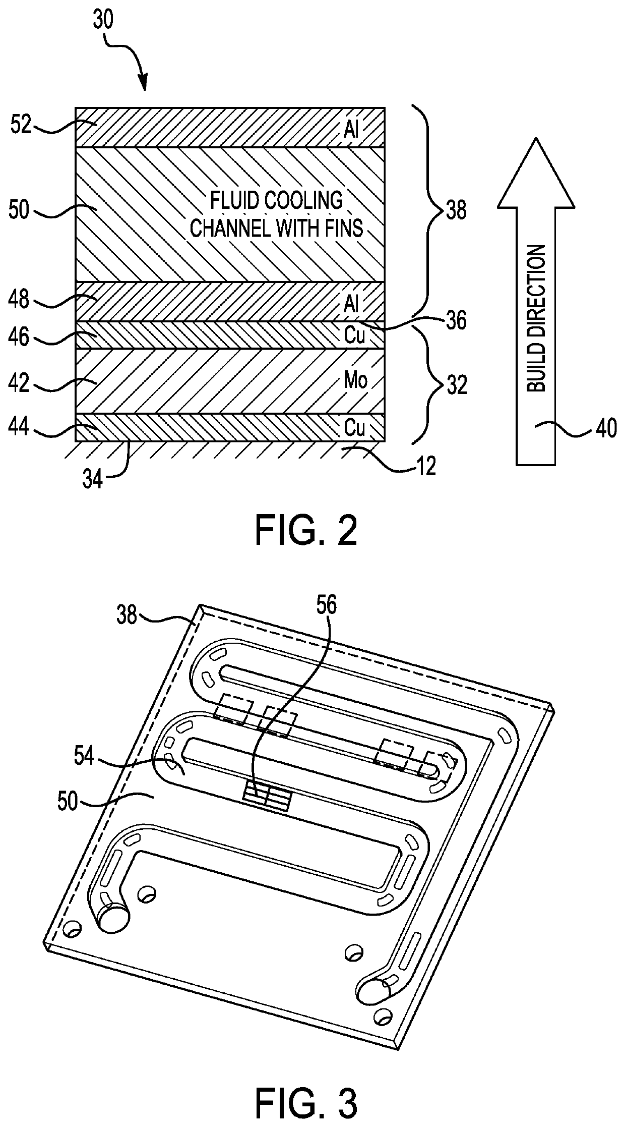
[0043]Ultrasonic additive manufacturing (UAM) is advantageous in forming cooling structures due to the capabilities of UAM in producing complex internal features within metallic materials and the materials available for UAM. Using UAM is advantageous in forming intermetallic bonding that inc...


PUM

PropertyMeasurementUnit
Surface areaaaaaaaaaaa
Heataaaaaaaaaa

Abstract

A method of forming a cooling structure for a heat-dissipating surface includes arranging a heat spreader layer adjacent the heat-dissipating surface, bonding a coldplate directly to the heat spreader layer opposite the heat-dissipating surface, and forming an intermetallic bond between the heat spreader layer and the coldplate. The coldplate is bonded to the heat spreader layer using ultrasonic additive manufacturing.

Description

FIELD OF THE INVENTION[0001]The invention relates to structures manufactured using ultrasonic additive manufacturing, and more particularly, forming a cooling structure having a heat spreader and a coldplate that is directly bonded to the heat spreader material.DESCRIPTION OF THE RELATED ART[0002]Many applications use cooling structures or manifolds for cooling a heat-dissipating surface. A conventional cooling method includes using forced convection coldplates that are in contact with a heat-dissipating surface. However, using only forced convection coldplates may not be suitable for use in some applications, such as in high-power electronics having chips that dissipate an extremely high heat flux.[0003]Attempts have been made to provide cooling for chips in high-power electronics applications. One attempt includes providing a heat spreader material for spreading heat across a surface area that is larger than the surface area of the heat-dissipating surface prior to cooling using f...

Claims


Application Information

Patent Timeline
IPC IPC(8): B23K20/10H01L21/48H01L23/427B33Y10/00B33Y70/00B33Y80/00
CPCB23K20/10H01L21/4882H01L23/427B23K2103/10B33Y70/00B33Y80/00B33Y10/00H01L23/3735H01L23/3736H01L23/473H01L21/4871B22F5/006B23K20/103B23K2101/14H01L23/3672H01L23/3675B23K20/106H01L23/367
Inventor MAYBERRY, TRAVIS L.MCCORDIC, CRAIG H.ELLSWORTH, JOSEPH R.
Owner RAYTHEON CO
Why Eureka
Try Eureka