Apparatus and method for temperature controlled cold spray

a technology of temperature control and apparatus, applied in the direction of heat inorganic powder coating, coating, additive manufacturing, etc., can solve the problems of increasing the difficulty of thermal control to establish consistent thermal environments for the cold spray process, complicated model heat shedding, etc., to improve the deposition properties, improve the temperature control, and improve the effect of deposition properties

Pending Publication Date: 2021-06-24
NAT RES COUNCIL OF CANADA
View PDF2 Cites 6 Cited by
  • Summary
  • Abstract
  • Description
  • Claims
  • Application Information

AI Technical Summary

Benefits of technology

[0013]Applicant has discovered a process of cold spray deposition with better control over deposition properties (i.e. adhesion, cohesion, density, thickness, deposition efficiency and microstructure), that allows for a wider variety of acceptable deposition parameters and therefore a larger space of tool paths to deposit or additively manufacture a part, and permits CS deposition on substrates with complicated geometries. The process relies on improved temperature control during deposition, by way of feedback. Temperature control has many advantages, including the ability to improve deposition properties without changing deposition parameters and therefore provides an additional control that affects deposition. Temperature control can quickly react to ensure desired deposition properties. Thermal feedback for controlling CS deposition can be provided with a laser (preferably pulsed), and a remote temperature sensor capable of instantaneous measurement (e.g. an infrared camera or a pyrometer), which is calibrated for or corrected for variation in surface emissivity. During cold spray deposition, temperature of the sprayed surface is monitored, and fed to a controller. The controller has software for receiving real-time temperature measurements, and outputs feedback t

Problems solved by technology

When the surface topology of the part is complex, modelling heat shedding can be more complicated.
When the part is additively manufactured with a substantial depth o

Method used


Image

  • Apparatus and method for temperature controlled cold spray
  • Apparatus and method for temperature controlled cold spray
  • Apparatus and method for temperature controlled cold spray

Examples


example 1

Copper CS Deposition on Circular Plates

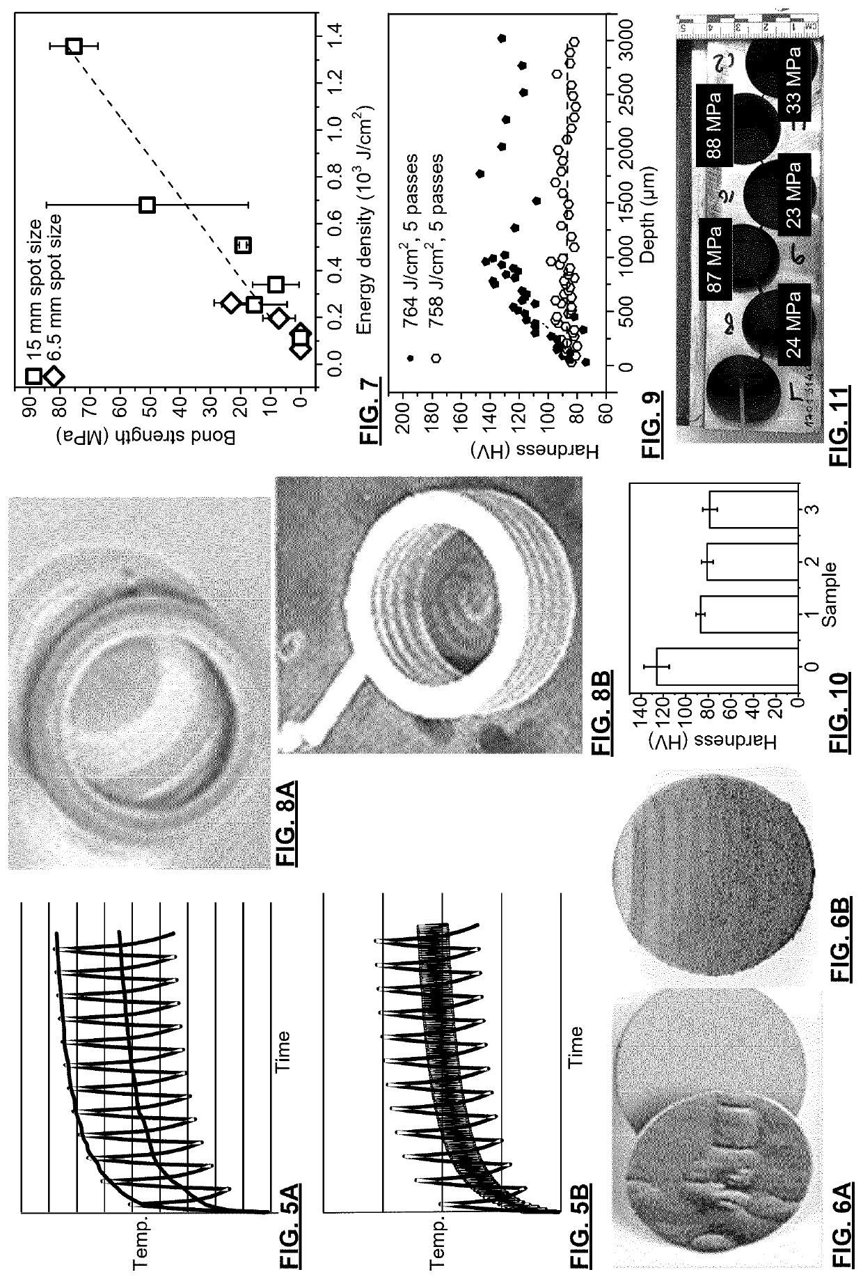
[0104]FIG. 6A is a photograph of a delaminated copper coating that was CS deposited onto a mild steel substrate deposited without laser assistance. FIG. 6B is a photograph of a copper coating deposited on the same substrate with continuous laser assistance. Both coatings were produced using Inovati™ (Santa Barabara, Calif.) low pressure CS gun using nitrogen at 300° C. and 90 PSI with the gun traverse speed of 10 mm / s. The surface of the samples were grit blasted using alumina grit 60 particle in preparation for the deposition. In depositing the coating shown FIG. 6B the first pass used a laser beam spot size (at surface) of 6 mm and power of 750 W. Subsequent passes did not have any laser assisted heating. The adhesion improved as the coating remains on the coupons after deposition. Visual inspection showed that the coating is oxidized (darker color).

example 2

Power Density Vs Bond Strength

[0105]A study of the effect of power density of continuous lasers on bond strength of coatings was performed. Coatings were produced by cold spray of commercially pure copper powder using Plasma Giken™ PVS-800 gun at 800° C. and 4.9 MPa pressure Nitrogen. A stand-off distance of 30 mm was used for the cold spray gun. The laser power varied and two lasers were used one 4 kW and one 1.6 kW. Laser spot sizes were 6.5 and 15 mm. The laser and the cold spray gun were mounted on the same robot and the displacement velocity (10 mm / s and 300 mm / s) were varied. Overall, increased energy density leads to improved adhesion, as seen in FIG. 7. The effect of surface temperature is noticeable. Even with 4 kW power at 300 mm / s, there is no adhesion of copper to the mild steel, but at lower speed (10 mm / s), even with lower (1.6 kW) power, the bond strength exceeds the test capabilities, and it is a glue that fails before the coating delaminates.

example 3

Pulsed Laser Vs. No Assisted Heating Surface Adhesion of AM Rings

[0106]FIGS. 8A,B are photographs of CS additively manufactured part (ring) adhesion on a mild steel substrate by cold spray. In these tests, AM rings were placed on mild steel substrates and cold sprayed along their interface in an effort to join the rings to the substrates. To improve adhesion, the mild steel substrate shown in FIG. 8A was grit blasted using grit 24 alumina, but the substrate was not grit blasted in the example of FIG. 8B. In both cases, cold spray was deposited with a zigzag pattern with 1 mm step size. The traverse speed was 50 mm / s. The cold spray jet from the Inovati gun was about 480° C., and 120 psi. The stand-off was 15 mm giving a laser spot size of about 6 mm. Both the particle jet and the laser jet were supperposed. The embodiment of FIG. 8B was different only in that the substrate was not grit blasted (used as-received), and for the 1st pass only a 4 kW, 10 Hz, 10 ms (400 J / cm2) pulsed lase...


PUM

PropertyMeasurementUnit
Timeaaaaaaaaaa
Timeaaaaaaaaaa
Timeaaaaaaaaaa

Abstract

A technique for improving cold spray deposition conditions for cold spray additive manufacture of parts involves providing an in-situ temperature feedback controller with a remote instantaneous temperature sensor supplying surface temperature measurements of the deposition surface, and a (preferably long pulse) laser for heating. Temperature feedback allows for control over deposition conditions yielding predictable deposition properties.

Description

FIELD OF THE INVENTION[0001]The present invention relates in general to laser-assisted cold spray deposition and, in particular, to the use of feedback for thermal regulation and improved cold spray deposition to improve a range of the cold spray deposition conditions, for spraying on parts having complex topography, or additive manufacturing.BACKGROUND OF THE INVENTION[0002]Cold spray (CS) is an industrialized process for applying coatings and to dimensionally restore parts, and holds promise for additive manufacturing, however a lack of consistency, most notable in the fabrication of large and complex parts, is a substantial limitation to broader utilization. CS is a method of depositing (usually metallic or ceramic-metallic composite) materials by accelerating solid powders in a supersonic gas jet and propelling the jet towards a substrate. During impact with the substrate (or previously deposited layer), particles undergo plastic deformation and adhere to the surface to build-up...

Claims


Application Information

Patent Timeline
IPC IPC(8): B22F10/85B22F12/49B22F12/53B22F12/43B22F12/90B22F12/13B22F10/38B22F10/364B33Y10/00B33Y30/00B33Y40/10B33Y40/20B33Y50/02
CPCB22F10/85B22F12/49B22F12/53B22F12/43B22F12/90B22F12/13B22F2203/11B22F10/364B33Y10/00B33Y30/00B33Y40/10B33Y40/20B33Y50/02B22F10/38C23C24/00C23C24/08C23C24/04B05B7/1486Y02P10/25
Inventor IRISSOU, ERICLEGOUX, JEAN-GABRIELCOJOCARU, CRISTIAN VICTORILINCA, FLORINBOURNIVAL, SYLVAIN
Owner NAT RES COUNCIL OF CANADA
Why Eureka
Try Eureka