Electronic power module assemblies and control logic with direct-cooling vapor chamber systems

a technology of electrical power module and control logic, which is applied in the direction of battery/fuel cell control arrangement, transportation and packaging, propulsion by batteries/cells, etc., can solve the problems of concomitant increase of power density and operational life expectancy of hv electrical systems, and achieve efficient direct cooling, increase the power density and operational life expectancy of hv electrical systems, and optimize thermal management

Active Publication Date: 2021-06-24
GM GLOBAL TECH OPERATIONS LLC
View PDF0 Cites 1 Cited by
  • Summary
  • Abstract
  • Description
  • Claims
  • Application Information

AI Technical Summary

Benefits of technology

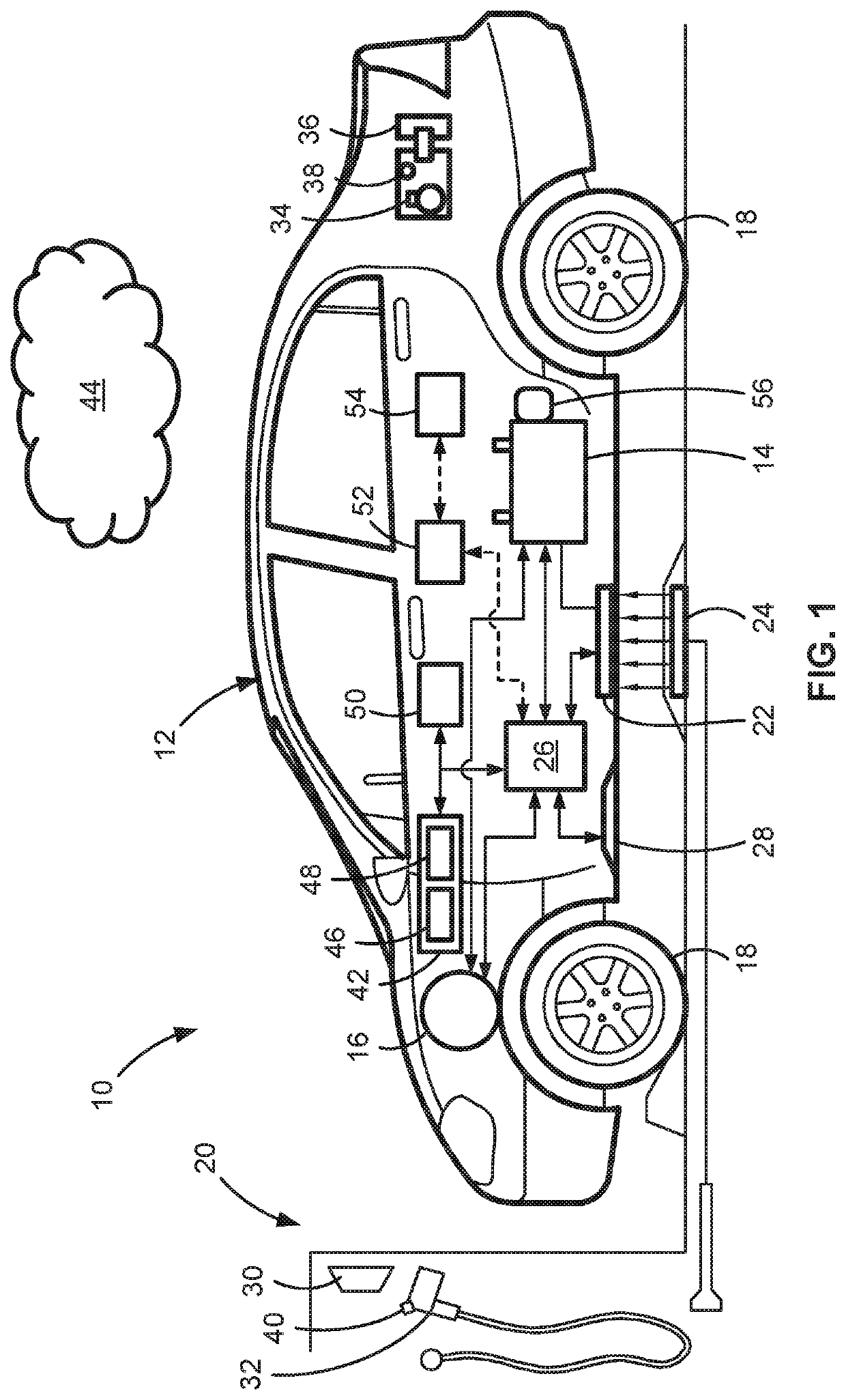
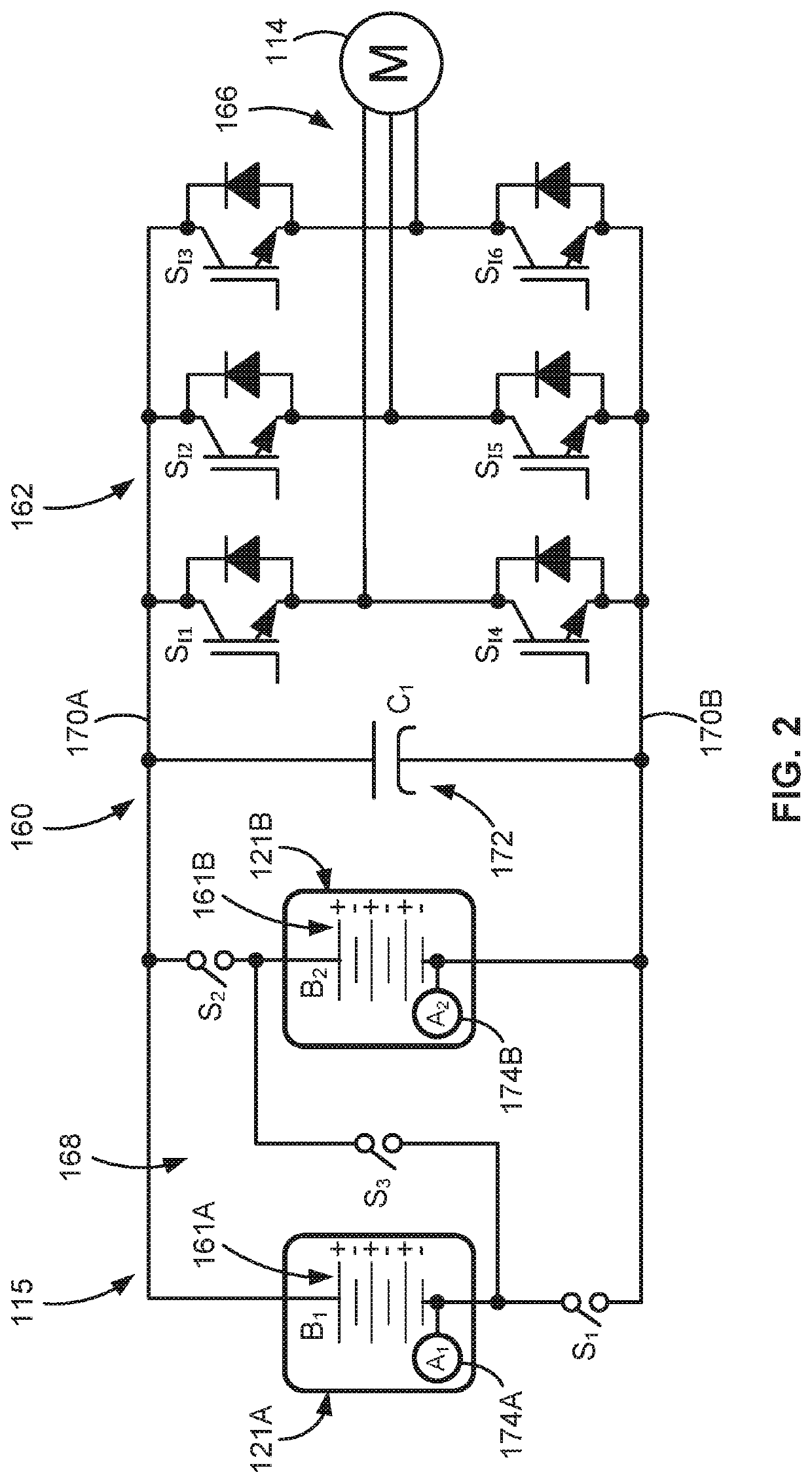
[0007]Attendant benefits for at least some of the disclosed concepts may include novel power module packaging designs that provide efficient direct cooling to opposing sides of each power device for optimized thermal management. In so doing, disclosed power module designs concomitantly increase the power density and operational life expectancy of the HV electrical system. Disclosed direct-cooling vapor chamber systems enable the power module to use high-voltage insulated gate bipolar transistors (IGBT) and wideband gap (WBG) devices, which in turn helps to improve powertrain performance. Other attendant benefits may include power module architectures that help to minimize electrical system complexity and associated costs while reducing gross vehicle weight and providing a more efficient powertrain system with improved vehicle range and fuel economy.

Problems solved by technology

In so doing, disclosed power module designs concomitantly increase the power density and operational life expectancy of the HV electrical system.

Method used


Image

  • Electronic power module assemblies and control logic with direct-cooling vapor chamber systems
  • Electronic power module assemblies and control logic with direct-cooling vapor chamber systems
  • Electronic power module assemblies and control logic with direct-cooling vapor chamber systems

Examples


Embodiment Construction

[0023]This disclosure is susceptible of embodiment in many different forms. Representative embodiments of the present disclosure are shown in the drawings and will herein be described in detail with the understanding that these embodiments are provided as an exemplification of the disclosed principles, not limitations of the broad aspects of the disclosure. To that extent, elements and limitations that are described, for example, in the Abstract, Introduction, Summary, and Detailed Description sections, but not explicitly set forth in the claims, should not be incorporated into the claims, singly or collectively, by implication, inference or otherwise.

[0024]For purposes of the present detailed description, unless specifically disclaimed: the singular includes the plural and vice versa; the words “and” and “or” shall be both conjunctive and disjunctive; the words “any” and “all” shall both mean “any and all”; and the words “including,”“containing,”“comprising,”“having,” and the like,...


PUM


Abstract

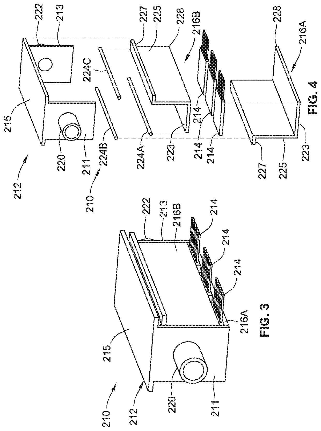
Presented are electronic power module assemblies with direct-cooling vapor chamber systems, methods for making/using such power module assemblies, and vehicles equipped with such power module assemblies. A power module assembly includes an outer housing with an internal coolant chamber that circulates therethrough a coolant fluid. A power semiconductor switching device is mounted to the module's housing, separated from the coolant chamber and isolated from the coolant fluid. The power device selectively modifies electric current transmitted between a power source and an electrical load. A two-phase, heat-spreading vapor chamber device includes an outer casing with a casing segment that is mounted to the module housing, fluidly sealed to the internal coolant chamber and exposed to the coolant fluid. Another casing segment includes an inboard-facing casing surface that is mounted to an outboard-facing surface of the power device, and an outboard-facing casing surface mounted to an inboard-facing surface of the power device.

Description

INTRODUCTION[0001]The present disclosure relates generally to high-voltage electrical power systems. More specifically, aspects of this disclosure relate to thermal management systems for traction power inverter modules (TPIM) of electrified vehicle powertrains.[0002]Current production motor vehicles, such as the modern-day automobile, are originally equipped with a powertrain that operates to propel the vehicle and power the vehicle's onboard electronics. In automotive applications, for example, the vehicle powertrain is generally typified by a prime mover that delivers driving power through an automatic or manually shifted power transmission to the vehicle's final drive system (e.g., differential, axle shafts, road wheels, etc.). Automobiles have historically been powered by a reciprocating-piston type internal combustion engine (ICE) assembly due to its ready availability and relatively inexpensive cost, light weight, and overall efficiency. Such engines include compression-ignit...

Claims


Application Information

Patent Timeline
Patent Type & Authority Applications(United States)
IPC IPC(8): H05K7/20B60L50/51B60L50/60
CPCH05K7/20881B60L50/51B60L2210/40H05K7/20936H05K7/20327B60L50/60H01L23/49548H01L23/49568H01L23/49575H01L23/467B60L58/21B60L2240/525B60L15/007Y02T10/64
Inventor LIU, MINGCOPPOLA, ANTHONY M.SONTA, KESTUTIS A.
Owner GM GLOBAL TECH OPERATIONS LLC
Why Eureka
Try Eureka