

Filling nozzle
Pending Publication Date: 2021-07-29
CHUGAI PHARMA CO LTD
View PDF1 Cites 0 Cited by
- Summary
- Abstract
- Description
- Claims
- Application Information
AI Technical Summary
Benefits of technology
The present invention provides a filling nozzle that prevents solid components from sticking to its tip, allowing for the stable production of liquid pharmaceutical formulations. Additionally, the method for producing liquid pharmaceutical formulations using this filling nozzle is efficient and cost-effective.
Problems solved by technology
When a prescribed amount of liquid is continuously filled in a vessel in the filling step, there arises a problem of dripping from the tip of the filling nozzle.
The dripping from the tip of the filling nozzle contaminates a product to be produced, contaminates the production environment, and lowers filling accuracy, which may cause product quality deterioration or productivity deterioration.
In particular, a liquid pharmaceutical formulation of a protein solution cannot be subjected to a sterilization step by heating or radiation exposure after the filling.
In an aseptic environment employed for pharmaceutical production, air having passed through a high efficiency particulate air filter (HEPA filter) is circulated, and hence, there arises a problem in which a pharmaceutical solution adhering to the tip of a filling nozzle is dried.
When a pharmaceutical component thus dried adheres to the tip of the filling nozzle, lowering of filling accuracy, contamination of a product to be produced, contamination of the production environment, and clogging of the filling nozzle occur, which may cause deterioration of the product quality and deterioration of the productivity.
In particular, when the filling nozzle is clogged by adhesion of the dried pharmaceutical component, the production cannot be continued because the pharmaceutical solution cannot be discharged through the filling nozzle.
In this case, the production of the pharmaceutical or the aseptic environment is intermitted once for restoration, and therefore, it is necessary to discard a production lot, to discard a prepared pharmaceutical solution, or to decontaminate the aseptic environment, which causes a large loss economically and in time.
Even when the suck-back is employed, however, the liquid adhering to the inner wall of the filling nozzle may move to and stagnate at the tip of the filling nozzle, and hence a dried pharmaceutical component is accumulated to cause the clogging in some cases.
Method used
View moreImage
Smart ImageViewing Examples

Examples
text example 12
[0348]FIG. 24 illustrates a lower end liquid surface of a pharmaceutical solution stagnating in a filling nozzle and a nozzle lower end obtained by using the filling nozzle cop_1 for filling the antibody formulation A (about 1.2 mL) in a vessel by using the filling pump B. A pumping rate in the filling was set to 200 rpm, and the suck-back was performed in the filling. It was confirmed that the liquid surface height of the solution (droplet) stagnating in the filling nozzle measured when the lower end liquid surface (gas-liquid interface) of the stagnating solution was settled after the filling was in a higher position than the lower end of the filling port (FIG. 24(c)).
Login to View More PUM
| Property | Measurement | Unit |
|---|---|---|
| Water contact angle | aaaaa | aaaaa |
| Water contact angle | aaaaa | aaaaa |
| Diameter | aaaaa | aaaaa |
Abstract
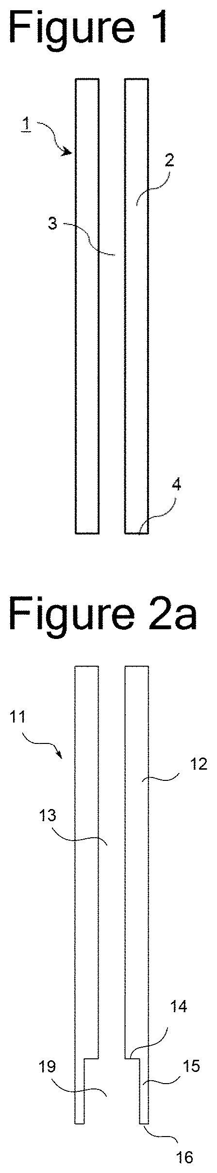
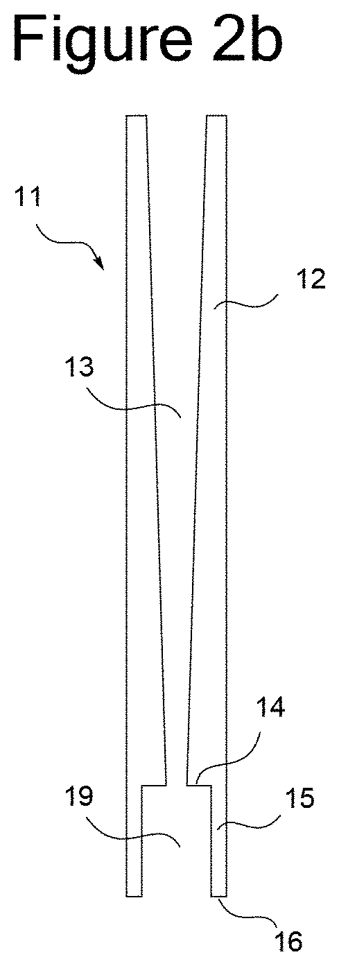
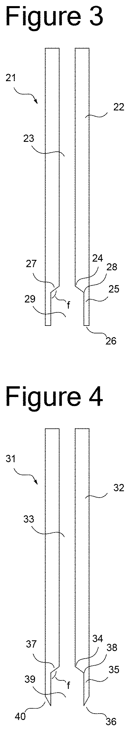
The present invention provides a filling nozzle obtained by using a resin selected from a cycloolefin polymer and a cycloolefin copolymer, or a filling nozzle including a tubular passage for supplying a pharmaceutical solution, and a filling port disposed at a lower end of the tubular passage, in which the tubular passage and the filling port have a circular peripheral cross-section, and an inner diameter of the passage of the filling port is larger than an inner diameter of the tubular passage disposed on an upstream side.
Description
TECHNICAL FIELD[0001]The present invention relates to a filling nozzle to be used for filling a liquid in a vessel. The present invention also relates to a production method for a product including a liquid filling step. In particular, the present invention relates to a filling nozzle to be used for filling a pharmaceutical solution in a vessel, and a production method for a liquid pharmaceutical formulation including a step of filling a pharmaceutical solution in a vessel.BACKGROUND ART[0002]In production of food, daily necessities, pharmaceuticals and the like, a solution held in a filling tank is filled with a pump in a vessel through a filling tube or a filling nozzle in a step of filling a liquid in a vessel. As a material for forming a filling nozzle to be used in production of a pharmaceutical, stainless steel or a resin such as polyether ether ketone (PEEK) is generally used.[0003]When a prescribed amount of liquid is continuously filled in a vessel in the filling step, ther...
Claims
Login to View More Application Information
Patent Timeline
 IPC IPC(8): B65B39/00B65B3/04B05B15/65B05B15/525B65B3/00
CPCB65B39/00B65B3/04B65B3/003B05B15/525B05B15/65B65B3/14B65B3/36B67C3/28B01J4/02B01J2204/005B67C3/02B05B15/50C08L45/00C08L23/08A61K2039/505
InventorNISHIZAWA, SHAW
OwnerCHUGAI PHARMA CO LTD