Microfluidic module for co-encapsulation in droplets

a technology of microfluidic modules and droplets, which is applied in the field of microfluidic modules for co-encapsulation in droplets, can solve the problems of inability to control the content of merged droplets, the size of droplets must be related, and the inability to validate all manipulations, etc., to avoid the merging of droplets, high yield, and high throughput

Pending Publication Date: 2021-08-05
UNIV LIEGE
View PDF0 Cites 0 Cited by
  • Summary
  • Abstract
  • Description
  • Claims
  • Application Information

AI Technical Summary

Benefits of technology

[0009]According to a first aspect, one of the objects of the present invention is to provide a microfluidic module in order to avoid merging of droplets with unwanted or no content. The present invention allows for co-encapsulation in droplets with a high yield from two populations of encapsulating droplets. Another object of the invention is to provide a microfluidic module for co-encapsulation in droplets with encapsulating droplets of different sizes. Another object of the invention is to provide a microfluidic module for co-encapsulation in droplets allowing a high throughput with a high flexibility regarding the number of co-encapsulated droplets.

Problems solved by technology

This can go as far as invalidating all manipulation if the cells are too rare and their sequencing is not allowed due to lack of sufficient DNA.
A drawback of this co-encapsulation merging unit is that the droplets size must be related to the micro-cavities traps sizes.
A drawback of this microfluidic chip is that it does not allow a good control of the content of the droplets to be merged and thus of the content of the merged droplets.
Another drawback is that the merged droplets are washed out from one of the outlet, which means that there cannot be a continuous merging process with this microfluidic chip.
A drawback of this droplet merging module is that is does not allow a good control of the content of the merged droplets because it does not allow to sort generated droplets before they reach the droplet merging module.

Method used


Image

  • Microfluidic module for co-encapsulation in droplets
  • Microfluidic module for co-encapsulation in droplets
  • Microfluidic module for co-encapsulation in droplets

Examples


Embodiment Construction

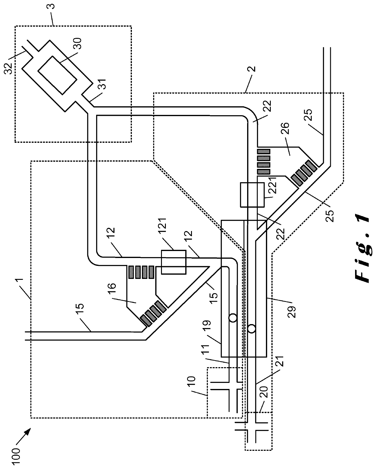
lass="d_n">[0133]FIG. 1 shows a schematic diagram of an embodiment of the microfluidic module 100 of the invention. The microfluidic device 100 comprises a first module 1, for generating, encapsulating, sorting and providing to the fusion module 3 a droplet of a first population to be merged with another droplet in the fusion module 3. The microfluidic device 100 comprises a second module 2, for generating, encapsulating, sorting and providing to the fusion module 3 a droplet of a second population to merge with another droplet in the fusion module 3. The first 1 and second 2 modules each comprise a generation and encapsulation module 10, 20 able to provide in respective inlets 11, 21, encapsulated droplets of a first and second population respectively. The first 1 and second 2 module inlets 11, 21 respectively each have a detection portion 19, 29 which allows visualizing generated and encapsulated droplets in these inlets 11, 21. The visualization through these detection portions 1...


PUM

PropertyMeasurementUnit
diametersaaaaaaaaaa
diametersaaaaaaaaaa
outer diametersaaaaaaaaaa

Abstract

A microfluidic module for co-encapsulation in droplets of two populations of particles may include first and second modules for sorting the two populations. The modules may have their first outlets including first obstructive valves configured to at least partially obstruct the first outlets. The first outlets may be fluidly connected to a fusion module, including a fusion module means for merging at least one droplet from the first droplet population and at least one droplet from the second droplet population into a merged droplet comprising the two population of particles, and a control unit for controlling the first obstructive valves from information originating from a first and second module detection portion located upstream of the first outlets.

Description

TECHNICAL AREA[0001]According to a first aspect, the invention relates to a microfluidic module for co-encapsulation in droplets.PRIOR ART[0002]Microfluidics is the manipulation of fluids at the micrometre scale, in dedicated devices referred to in general as microfluidic chips. It is particularly well adapted to research and development in biology- and chemistry-related fields. Droplets of volume as small as a few picoliters can be produced in a microfluidic chip thanks to the immiscibility of two liquids, such as oil and water for instance. Aqueous droplets can be produced in an immiscible continuous oil phase (water-in-oil droplets). Reciprocally, oil droplets could be formed in an aqueous phase (oil-in-water droplets). The field that consists in creating and using droplets in microfluidics is referred to as droplet microfluidics, also referred as two-phases, segmented, or droplet-based microfluidics.[0003]Monodisperse droplets (i.e. with same volume, spacing and frequency) are c...

Claims


Application Information

Patent Timeline
Patent Type & Authority Applications(United States)
IPC IPC(8): B01J13/08B01F3/08B01F13/00B01F15/02B01F15/00
CPCB01J13/08B01F3/0807B01F13/0071B01F13/0061B01F2215/0037B01F15/00344B01F15/00259B01F2003/0834B01F2003/0842B01F15/026B01J13/04B01F23/41B01F33/301B01F33/3021B01F35/214B01F35/2211B01F35/71805B01F23/4143B01F23/4145B01F2101/23
Inventor GILET, TRISTANVAN LOO, STÉPHANIE
Owner UNIV LIEGE
Why Eureka
Try Eureka