Unlock instant, AI-driven research and patent intelligence for your innovation.

Conveyor with Ejector

a technology of conveyors and ejectors, applied in the field of conveyors, can solve the problems of reducing the entire sorting system, presenting a risk of accidents, and reducing the size of the device, so as to reduce the danger of damage to the conveyor or the sorter/ejector, increase the throughput, and reduce the size

Active Publication Date: 2021-08-12
WIPOTEC GMBH
View PDF0 Cites 1 Cited by
  • Summary
  • Abstract
  • Description
  • Claims
  • Application Information

AI Technical Summary

Benefits of technology

The present invention provides a conveyor and sorter / ejector that increases throughput, reduces space requirements, and reduces the risk of damage or injury. The adjusting device allows for faster sorting and higher throughput by moving the ejector in the y direction to reduce the distance between the ejector and the products of a product flow. The design also reduces the risk of damage to the ejector and injury to operators, and reduces the space required in the y direction by using a telescoping pullout device. Additionally, the design allows for the ejector to operate as a stroke sorter or pusher, and as an air blast nozzle to blow off products that may be still in the production section.

Problems solved by technology

Because of this, the throughput of the entire sorting system is disadvantageously reduced.
Since the piston and cylinder device must extend out to its maximum stroke for the pusher plate to reach and divert the products, the device impedes the product flow until it has completely reached its starting position again.
In the retracted position, the piston rod then projects problematically across the transport direction of the belt conveyor and presents a risk of accident.
Also, the projecting rod can become accidentally damaged.
Moreover, the required pressure increases and gives rise to increased noise generation (up to a loud bang), which is perceived as disruptive in a working process.

Method used


Image

  • Conveyor with Ejector
  • Conveyor with Ejector
  • Conveyor with Ejector

Examples


Embodiment Construction

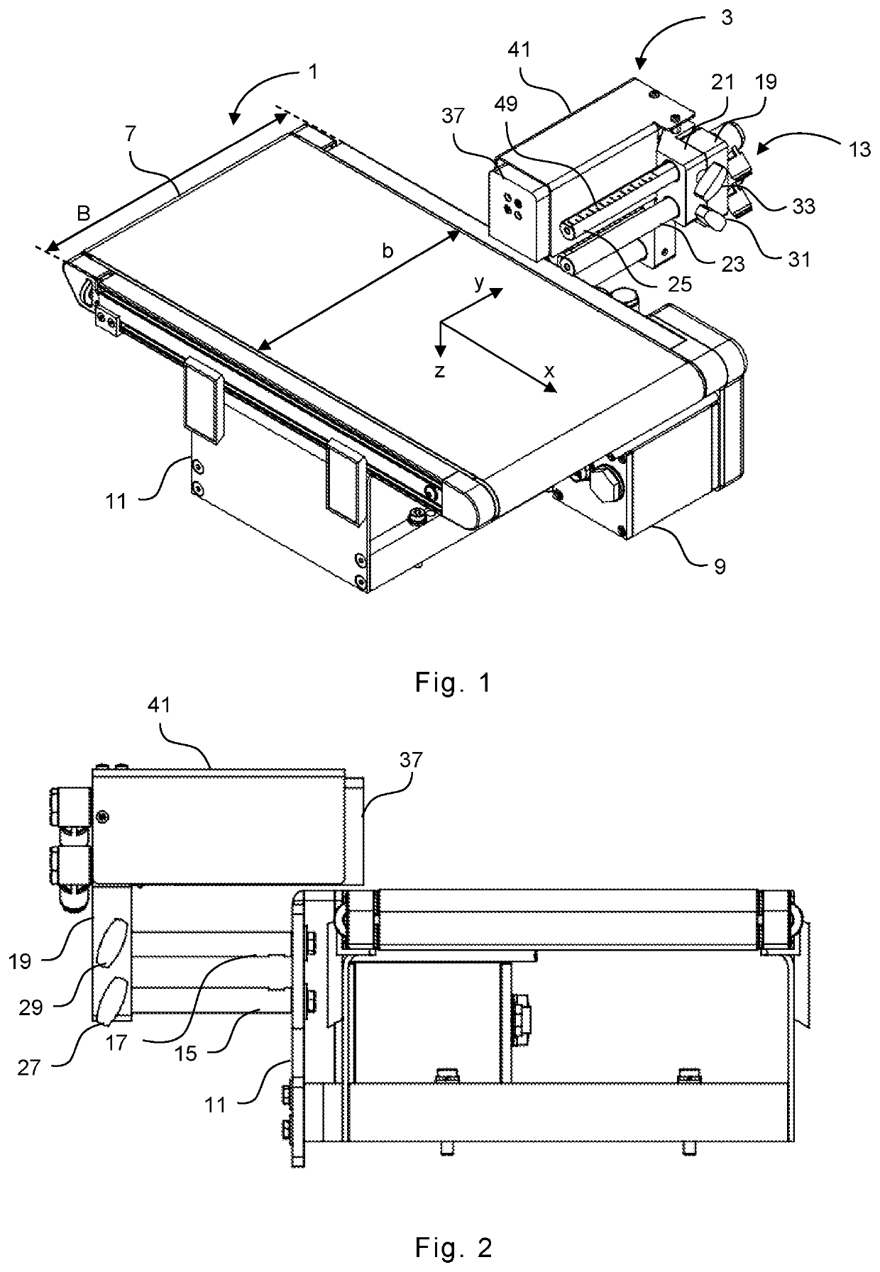
[0041]The conveyor 1 shown in FIG. 1, in this example a belt conveyor, comprises a frame 11 and a transport surface provided by a belt 7, which is guided over rollers (not shown in the drawing) at the left and right ends and driven in transport direction x by a motor 9 disposed on frame 11.

[0042]The belt conveyor 1 has a width B in the y direction transverse to the transport direction x. The belt 7 of the belt conveyor 1 lies within this width B, with a front and rear edge, so that the belt 7 has a correspondingly smaller width b.

[0043]At the rear side of the belt conveyor 1, approximately in the middle (in the x direction) region, an ejector in the form of a short stroke pusher 3 is mounted on the frame 11 by means of a mounting bracket which includes an adjusting device 13.

[0044]As can be seen from FIGS. 2, 4, 6, 8, and in particular 9, the adjusting device 13 includes a first and a second guide members, in this case guide cylinders 15 and 17 extending in the y direction to the re...


PUM


Abstract

A belt conveyor is configured for conveying products in a conveying direction and defines a width extending in a transverse direction orthogonal to the conveying direction, and a height direction orthogonal to the conveying and transverse directions. An ejector is fixed to the belt conveyor and acts in the transverse direction for sorting out / discharging products. The ejector has an end region which faces the product to be sorted out, and has a base body mounted in a base position on the belt conveyor by means of a holder. The basic position of the base body can be adjusted by means of an adjusting device of the holder in the transverse direction within an adjustment path so that the end area of the non-actuated ejector in the transverse direction can protrude across the belt conveyor width by at least half of that width, or more.

Description

TECHNICAL FIELD OF THE INVENTION[0001]The invention concerns conveyors for transporting products in a transport direction and having an ejector acting in the direction transverse to the transport direction in order to sort or divert products.BACKGROUND OF THE INVENTION[0002]Conveyors are used, for example, in production lines in the manufacture, testing, and control of packages or products, in order to automatically sort or divert from the product flow items that have been determined to be nonconforming.[0003]In this case, various kinds of sorting systems with various modes of operation can be used to sort products, for example, air blast nozzles, sorting gates, sorting paddles, or even sliders or pushers.[0004]Sliders or pushers usually use a pneumatic piston and cylinder device as the actuator, on which is mounted a pusher plate, which ejects the product upon extension of the piston and cylinder device across the direction of the product flow.[0005]The product flow is mostly reali...

Claims


Application Information

Patent Timeline
Patent Type & Authority Applications(United States)
IPC IPC(8): B65G47/82B65G43/08
CPCB65G47/82B65G43/08B65G47/525B65G2203/044B65G2203/041B65G2203/0233B65G15/00B65G47/256
Inventor WALTER, MARKUS JOCHENMÜLLER, LUKAS
Owner WIPOTEC GMBH