Auxiliary power supply circuit and power supply device
- Summary
- Abstract
- Description
- Claims
- Application Information
AI Technical Summary
Benefits of technology
Problems solved by technology
Method used
Image

Examples
first embodiment
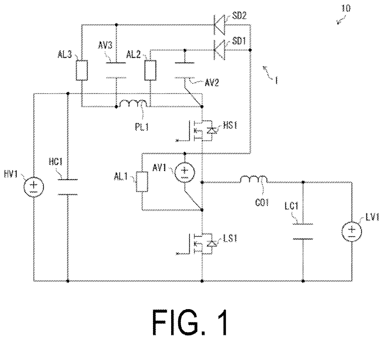
[0012]An auxiliary power supply circuit 1 and a power supply circuit 10 of a first embodiment will be described below with reference to FIG. 1. Note that, for convenience of description, in each embodiment hereinafter, components having the same functions as those of components described in the first embodiment are denoted using the same reference numerals, and descriptions thereof will not be repeated. For the sake of brevity, “power supply HV1” is also simply referred to as “HV1”, for example. Also, note that each numerical value described below is merely an example.
Definitions of Terms
[0013]Prior to describing the auxiliary power supply circuit 1, each term is defined in the present specification as follows.
[0014]“Power supply circuit”: A circuit that coverts power from a power supply on an input side to a power supply on an output side. As an example, a circuit that converts power from an AC230V power supply to a DC400V power supply. The power conversion includes, for example, a...
second embodiment
[0089]The auxiliary power supply circuit 1 according to one aspect of the present disclosure can also be used for reducing the switching loss to be generated in HS1 or LS1. Specifically, the switching loss is reduced by reducing the transient current generated at switching. The transient current here means, for example, a recovery current or a charging current for parasitic capacitance.
[0090]A power supply circuit 20 in FIG. 4 is a bidirectional DC / DC converter like the power supply circuit 10. In the power supply circuit 20, AL1 and AL2 are replaced with circuits for reducing transient currents to be generated in HS1 and LS1 with respect to the power supply circuit 10.
[0091]The circuit for reducing the transient current for HS1 will be described. An auxiliary switch AS2, an auxiliary coil AC2, and an auxiliary diode AD2 added around AV2 can reduce the transient current generated in HS1. The reduction method is as follows. First, by turning on AS2 before the transient current flows,...
third embodiment
[0094]The power supply circuit 10 according to one aspect of the present disclosure can be applied to an inverter circuit, a totem pole power factor correction (PFC) circuit, and the like, in addition to the bidirectional DC / DC converter.
[0095]FIG. 5 is a diagram illustrating a power supply device 100 provided with the power supply circuit 10. According to the auxiliary power supply circuit 1, an auxiliary power supply with reference to a high potential node can be provided to the power supply circuit 10 and the power supply device 100. Furthermore, the power supply circuit 10 includes the control circuit 9. The control circuit 9 controls the ON / OFF switching of the elements provided in the power supply circuit 10. In particular, the control circuit 9 controls ON / OFF switching of HS1 and LS1.
[0096]Supplement
[0097]An auxiliary power supply circuit according to a first aspect of the present disclosure receives power from an auxiliary power supply in which a negative electrode is conne...
PUM
 Abstract
Description
Claims
Application Information
 - R&D Engineer
- R&D Manager
- IP Professional
- Industry Leading Data Capabilities
- Powerful AI technology
- Patent DNA Extraction
Browse by: Latest US Patents, China's latest patents, Technical Efficacy Thesaurus, Application Domain, Technology Topic.
© 2024 PatSnap. All rights reserved.Legal|Privacy policy|Modern Slavery Act Transparency Statement|Sitemap