
Method, device, and computer program for improving synchronization of clocks in devices linked according to a daisy-chain topology

a technology of clock synchronization and daisy chain, which is applied in the direction of time-division multiplex, multiplex communication, electrical apparatus, etc., can solve the problems of master-slave synchronization suffering from unpredictable delay variation, synchronization of devices connected to the same communication network, and introduce time delay variation, so as to reduce the time duration needed for synchronizing the nodes, improve accuracy, and optimize the effect of clock synchronization

Active Publication Date: 2021-09-16
CANON KK
View PDF0 Cites 6 Cited by
  • Summary
  • Abstract
  • Description
  • Claims
  • Application Information

AI Technical Summary

Benefits of technology

The invention provides a method for optimizing synchronization of clocks in cascaded nodes, which reduces the time needed to synchronize the nodes. This method is compatible with the precision time protocol defined in IEEE 1588 and avoids duplicating the precision time protocol stack and the physical clock in the logical clock module and the time compensation clock module. Additionally, the invention includes a feature for improving the accuracy of the theoretical residence time by updating it as a function of the comparison.

Problems solved by technology

Synchronization of devices connected to the same communication network is a real challenge, in particular in control systems comprising interconnected nodes that have to be synchronized with the same time reference.
However, in a communication network wherein the different nodes are mostly interconnected through router or switch devices, the latter introduce time delay variation on the packet delivery according to the network traffic conditions.
Thus, the master-slave synchronization suffers from this unpredictable delay variation.
Furthermore, using different physical clocks per physical interface would imply not only duplicating the necessary resources (several PTP stacks, several timestamping modules, etc.) but also a complexity rise of the PTP management.
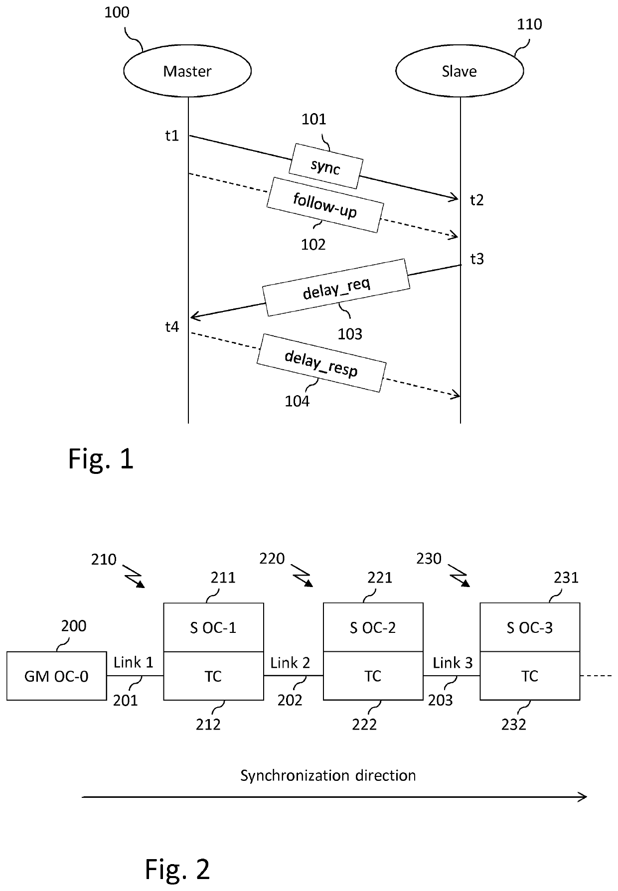
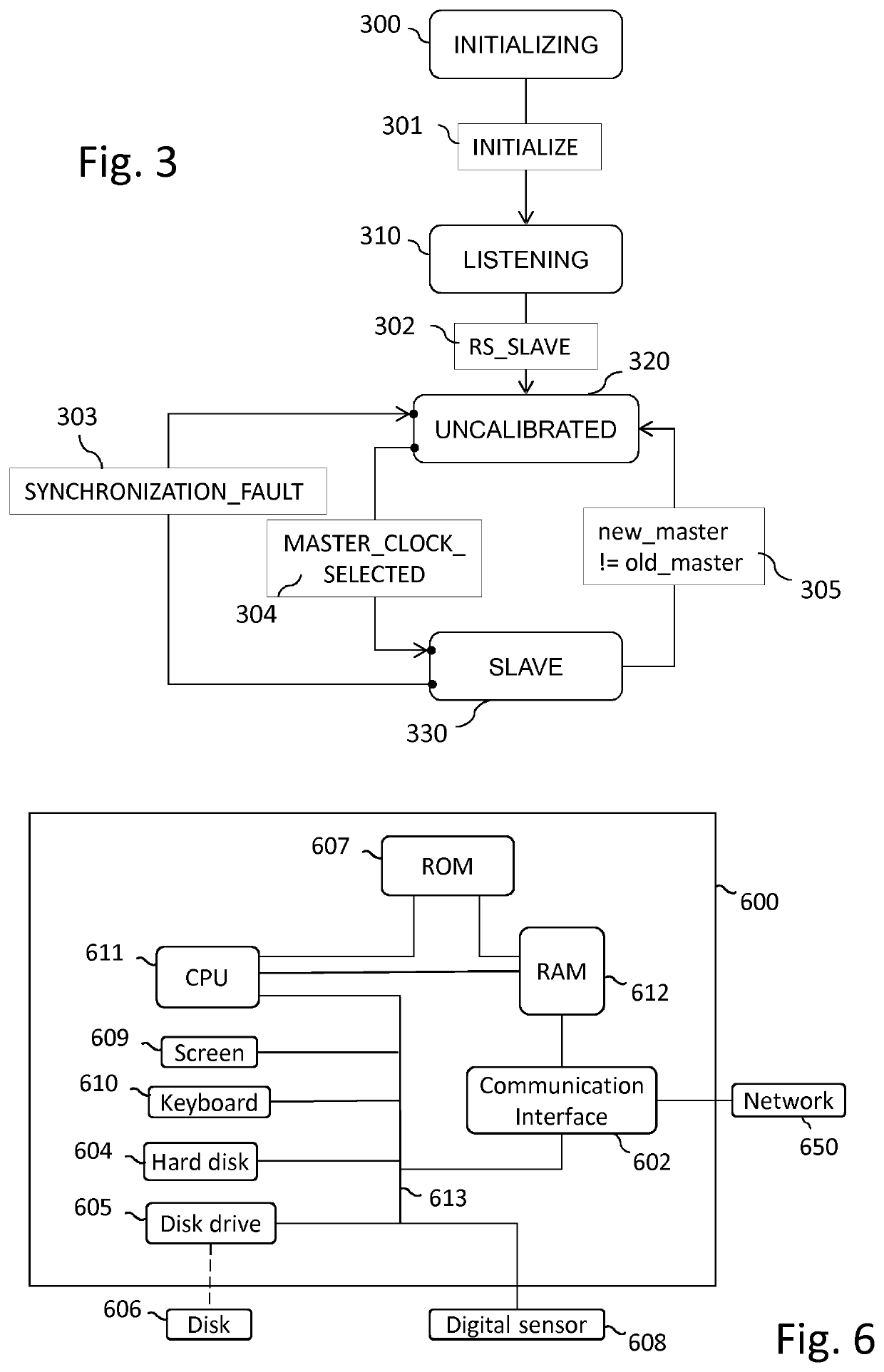
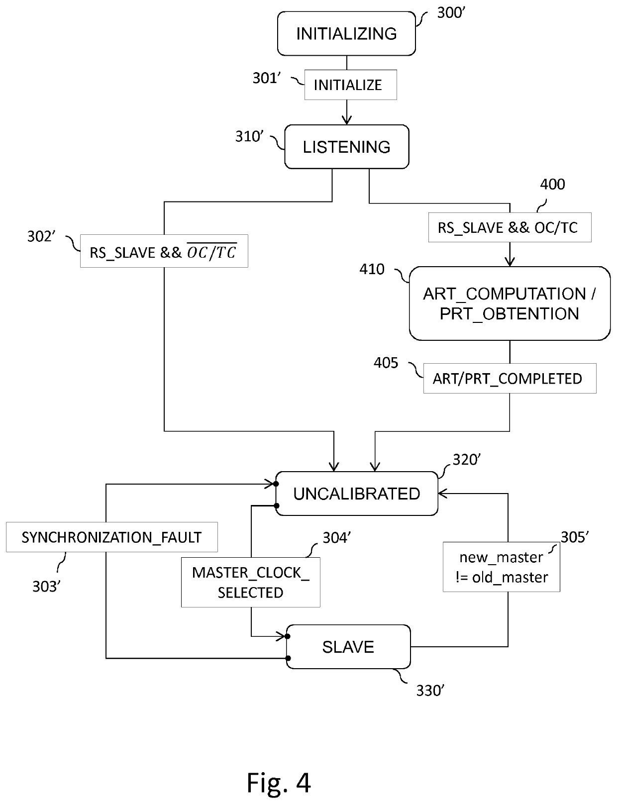
Although such a system may prove to be efficient, it has been observed that the combination of an ordinary clock and of a transparent clock leads to difficulties in particular circumstances, in particular during the calibration phase of the ordinary clock (corresponding to the UNCALIBRATED state).
However, these huge corrections to the physical clock introduce errors in the residence time computation by modifying the time of day while a synchronization message (e.g. Sync message 101 and Delay_Req message 103) is in transition or by using different clock values for ingress and egress timestamping.
Therefore, error in the residence time computation introduces inaccuracy in the offset and path delay computation for the following nodes.
Furthermore, since the slave nodes initialize their synchronization servos (servos being devices for maintaining a “position” according to an instruction, typically in IEEE 1588 a servo is implemented with a proportional integral derivative (PID) algorithm, a PID controller being a control loop feedback mechanism) during the calibration phase, they may be unable to converge and synchronize due to meaningless values of synchronization messages or packets.

Method used


Image

  • Method, device, and computer program for improving synchronization of clocks in devices linked according to a daisy-chain topology
  • Method, device, and computer program for improving synchronization of clocks in devices linked according to a daisy-chain topology
  • Method, device, and computer program for improving synchronization of clocks in devices linked according to a daisy-chain topology

Examples


Embodiment Construction

[0097]According to particular embodiments, the invention is directed to a synchronization mechanism for devices implementing a combination of a logical clock module used for synchronization purposes, for example an ordinary clock module in the broad meaning of the IEEE 1588-2008 standard, and of a time compensation clock module used for bridging purposes, for example a transparent clock module (still in the broad meaning of the IEEE 1588-2008 standard), where the logical clock module and the time compensation clock module share the same physical clock, using a theoretical residence time that may be predetermined or computed.

[0098]Still according to particular embodiments, start-up of the logical clock module synchronization is delayed so as to compute an average residence time while the physical clock is in a free running mode or is subject to an analog or a digital syntonization. The average residence time is advantageously used during synchronization of the logical clock module. N...


PUM


Abstract

At least one embodiment of a method for synchronizing a logical clock in a device comprising a physical clock, an input port, and an output port, the device further comprising a logical clock and a time compensation clock sharing the physical clock, the time compensation clock making it possible to determine a residence time, comprises:obtaining a theoretical residence time;during a pre-synchronization phase according to which the logical clock is not synchronized, adding a value representative of the obtained theoretical residence time to a residence time value stored in a synchronization message to be forwarded,during a synchronization phase according to which the logical clock is synchronized, obtaining a residence time and adding a value representative of the obtained residence time to a residence time value stored in a synchronization message to be forwarded, andsynchronizing the logical clock as a function of a residence time value stored in a received synchronization message.

Description

FIELD OF THE INVENTION[0001]The present invention relates to the technical field of clock synchronization in network connected devices and more particularly to a method, a device, and a computer program for improving synchronization of clocks in devices linked according to a daisy-chain topology.BACKGROUND OF THE INVENTION[0002]Synchronization of devices connected to the same communication network is a real challenge, in particular in control systems comprising interconnected nodes that have to be synchronized with the same time reference. The time reference is generally provided by a master node having a high precision clock that may be obtained, for example, from a connection to an atomic clock or to a Global Positioning System (GPS).[0003]The master node typically generates synchronization information related to its local clock (e.g. a frequency and / or a time of day) and sends this information to the other nodes (referred to as slave nodes) within synchronization messages or pack...

Claims


Application Information

Patent Timeline
IPC IPC(8): H04J3/06
CPCH04J3/0667H04J3/0641
Inventor GUIGNARD, ROMAINEL KOLLI, YACINELE SCOLAN, LIONELCLOSSET, ARNAUD
Owner CANON KK
Learn More