
Method for automated crack detection and analysis using ultrasound images

a crack detection and analysis technology, applied in the field of ultrasound images, can solve the problems of cracks in pipes, high risk of catastrophic failure of such pipes, and enormous engineering stresses on the equipment involved

Active Publication Date: 2021-11-04
SAUDI ARABIAN OIL CO
View PDF0 Cites 3 Cited by
  • Summary
  • Abstract
  • Description
  • Claims
  • Application Information

AI Technical Summary

Benefits of technology

The present patent provides a method and system for using high-resolution ultrasound images to predict the longevity of a pipe and when remediation measures need to be taken. The method involves capturing multiple ultrasound images of the pipe surface and preprocessing them using a computer vision algorithm to identify defects, such as cracks. The system then uses a machine learning process to determine parity relationships between the defects and predict the propagation of cracks along the pipe. The method and system can be trained using training data and can provide detailed static or time-lapsed images of the defects. The technical effects of this patent include improved prediction of pipe longevity and remediation measures needed, as well as improved efficiency and accuracy in identifying and tracking defects in pipes.

Problems solved by technology

The downhole geological conditions that are encountered in the process of petroleum extraction place enormous engineering stresses on the equipment involved.
These include high-amplitude, cyclic pressure loads which, combined with the highly corrosive environment, will gradually lead to the generation and eventual propagation of cracks in system pipes, ultimately posing a high risk of catastrophic failure of such pipes.
The incidence of cracks in the pipes of a hydrocarbon extraction and processing system is a process that begins insidiously, beginning when small defects in the microstructure of a pipe appear and initiate a process whose ultimate result is the dangerous undermining of the pipe's structural integrity.
This erosive damage is often attributable to a chemical process called hydrogen embrittlement, or hydrogen-induced cracking, which is the process of embrittlement of a metal after its exposure to hydrogen.
Theories proposed include that the exposure of a metal surface to hydrogen causes brittle hydrides to form within certain metals, resulting in the emergence of voids leading to bubbles and pressure build-up within a material, or even a hydrogen-induced enhanced decohesion of the material with resulting plasticity that promotes in the propagation of cracks.
Regardless of the actual mechanism that results in embrittlement of the material, chronic hydrogen exposure such as that seen in the petroleum industry clearly has a deleterious effect on the materials used to conduct the raw petroleum being extracted.
Over time, cracks can develop throughout the structure of oil pipelines, resulting in the structure becoming so compromised that the threat of a sudden, catastrophic failure, becomes a real possibility.
The losses attendant to such an event can be monumental, owing first to the cessation of production operations and then to the costs of remediation and repair, which may even include casualties among personnel and ancillary equipment.
Even though the image capture process is automated, the task of identifying cracks in the images obtained is daunting in both magnitude and analytical difficulty.
Even with the highest-quality ultrasound imagery available, a human reader of the images will be hard-pressed to make identifications of all but the most obvious, i.e., advanced and dangerous, cracks present within the surface of the pipe.

Method used


Image

  • Method for automated crack detection and analysis using ultrasound images
  • Method for automated crack detection and analysis using ultrasound images
  • Method for automated crack detection and analysis using ultrasound images

Examples


Embodiment Construction

[0024]The present disclosure concerns a method and system that can be used to analyze crack formations and predict the propagation of cracks on the surface of a pipe that have been identified by ultrasonography.

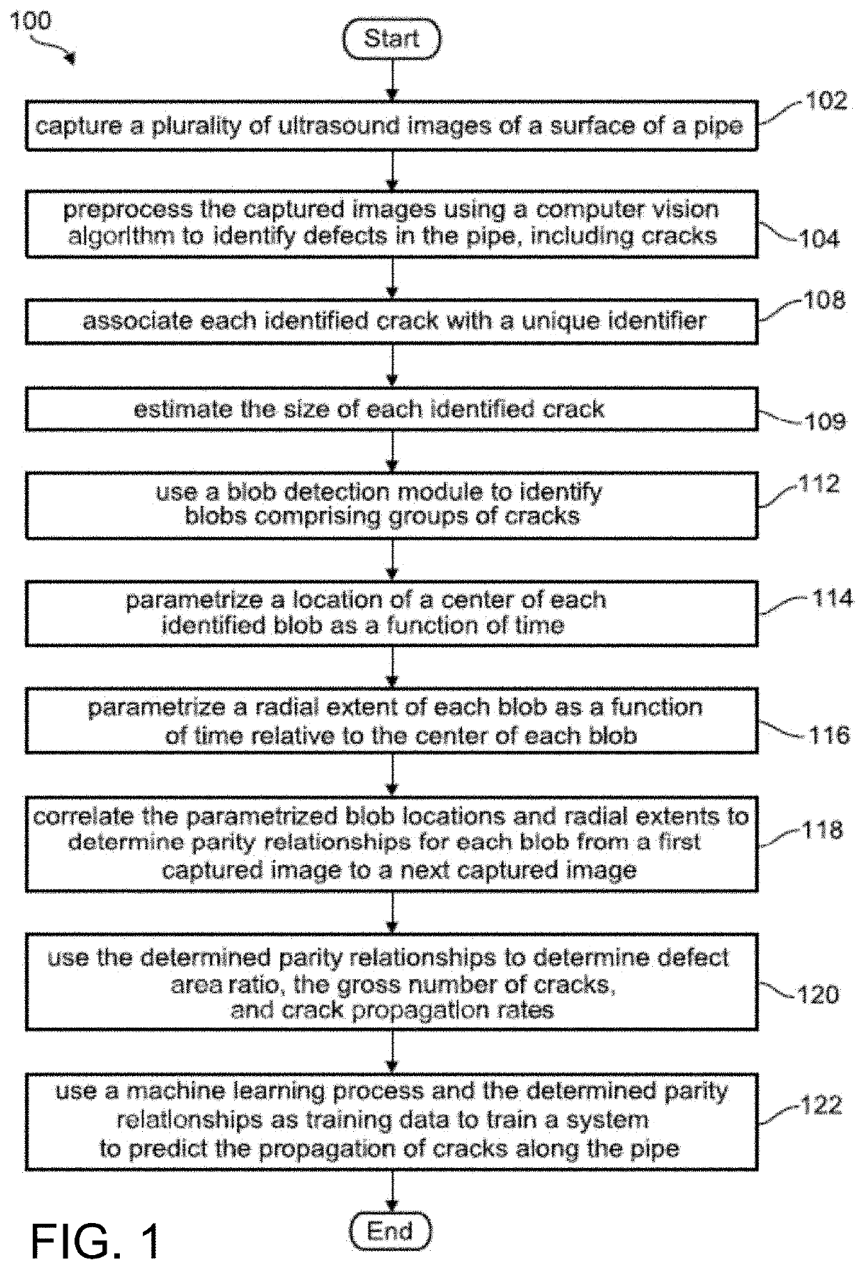
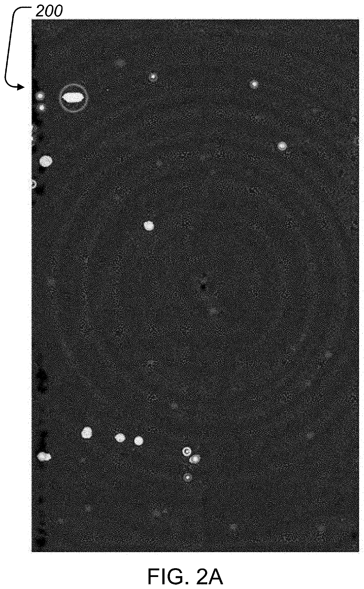
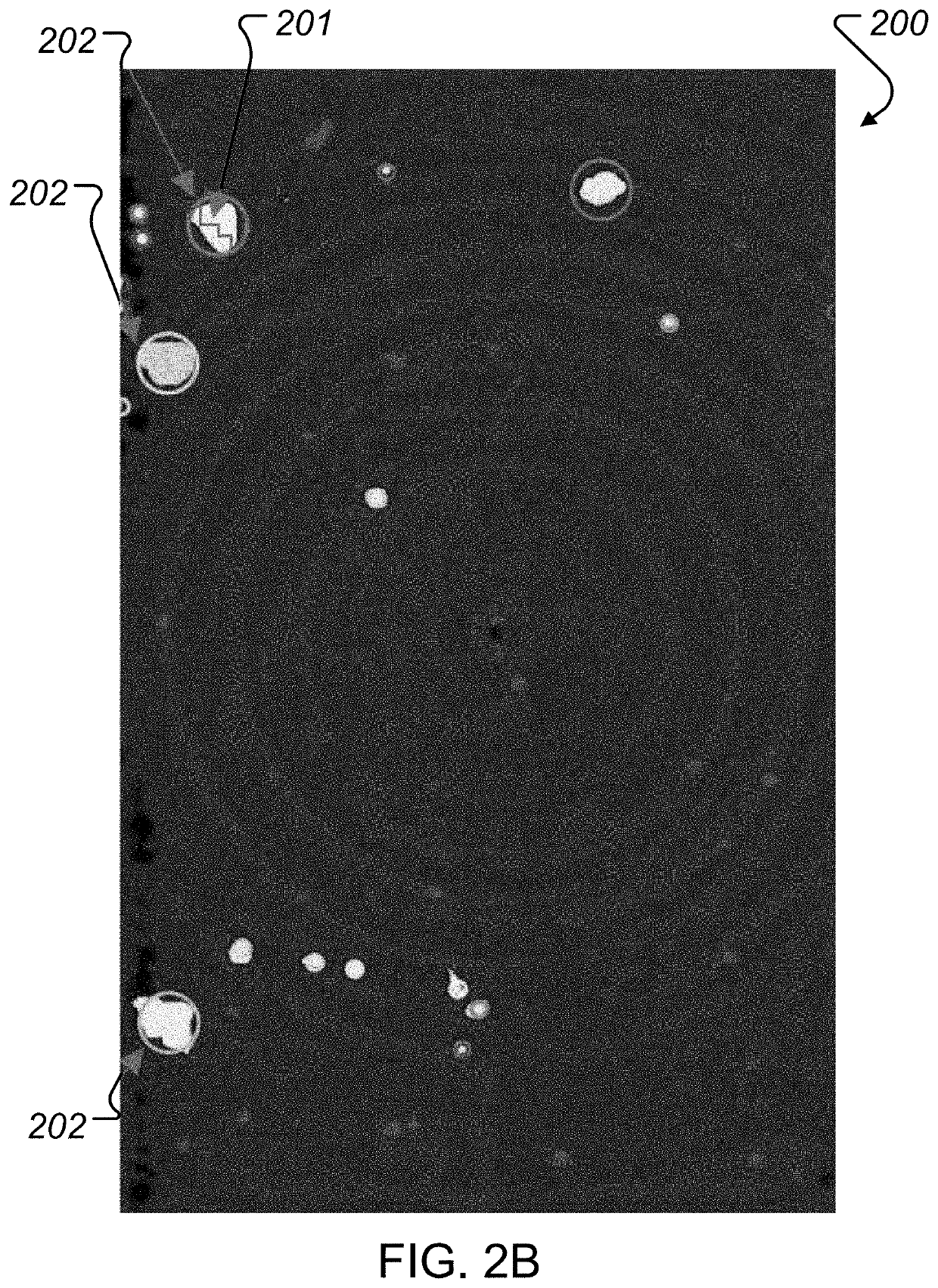
[0025]The method 100 of the present disclosure, which is shown schematically in FIG. 1, begins in step 102 by capturing a plurality of ultrasound images of at least one area of interest on a surface of the pipe. FIGS. 2A and 2B show two examples of ultrasound images 200 obtained by scanning selected areas of a surface of a pipe. Each of the two images reveal the presence of multiple blobs 202, which include areas where cracks or other defects 201 present within the surface of the pipe have created areas of detectable stress concentration. As each image is captured, it is indexed to the time and the position along the surface of the pipe at which the image was captured. Any suitable or convenient coordinate system can be used to record the exact position data corresponding to ...


PUM


Abstract

A computer-based method and system for predicting the propagation of cracks along a pipe is provided, wherein successive time-indexed ultrasound images of a pipe surface are captured and digitized. A computer vision algorithm processes the images to identify defects in the pipe, including cracks. At least one blob detection module is used to identify groups of cracks on the pipe surface that have created detectable areas of stress concentration or a prescribed likelihood of crack coalescence or crack cross-influence. The center locations and radial extents of respective blobs are each parametrized as a function of time and pipe surface location by determining parity relationships between successive digital data sets from successive captured images. The determined parity relationships are then used as training data for a machine learning process to train a system implementing the method to predict the propagation of cracks along the pipe.

Description

FIELD OF THE DISCLOSURE[0001]This patent application relates to methods for using ultrasound images to detect cracks in petroleum reservoir pipes, and, more particularly, to methods for predicting the propagation and potential merger of cracks along pipes through machine learning-enabled analysis of successive high-resolution ultrasound images of a pipe's condition.BACKGROUND OF THE DISCLOSURE[0002]Petroleum extraction is an endeavor in which the tools and machinery used as part of the process are exposed to extreme environments. A viscous, caustic fluid is extracted from below, oftentimes far below, the earth's surface under conditions of high pressure. The downhole geological conditions that are encountered in the process of petroleum extraction place enormous engineering stresses on the equipment involved. These include high-amplitude, cyclic pressure loads which, combined with the highly corrosive environment, will gradually lead to the generation and eventual propagation of cra...

Claims


Application Information

Patent Timeline
Patent Type & Authority Applications(United States)
IPC IPC(8): E21B47/002G06T7/00G06N3/08G06N20/00
CPCE21B47/002G06T7/0002G06T7/97G06T2207/20081G06N20/00G06T2207/10132G06T2207/20084G06N3/084G06T7/001G06T2207/30136G06T2207/30164G05B23/0283G01N29/041G01N29/069G01N29/4481
Inventor MOHAMED SHIBLY, KAAMIL UR RAHMANALDABBAGH, AHMAD
Owner SAUDI ARABIAN OIL CO
Learn More