
Storage system for radioactive nuclear waste with pressure surge protection

a technology of radioactive nuclear waste and storage system, which is applied in the field of storage system and storage system of high-level radioactive waste, can solve the problems of affecting the structural integrity of the containment provided, the quality of the containment is not perfect, and the storage of multiple fuel assembly units in the dry cask (“dry cask”) is not perfect, so as to protect the structural integrity of the cask, the effect of controlling and reducing the high pressure surge even

Active Publication Date: 2021-11-04
HOLTEC INT
View PDF0 Cites 2 Cited by
  • Summary
  • Abstract
  • Description
  • Claims
  • Application Information

AI Technical Summary

Benefits of technology

The wet cask system has a pressure control system to prevent high pressure in the cask during accidents or abnormal situations. This system has evacuated devices that can handle high pressure surges and protect the cask from damage.

Problems solved by technology

A gas filled dry cask (“dry cask”) holding multiple such fuel assembly units, however, is not perfect from the standpoint of controlling the temperature of the heat-emitting nuclear waste fuel because the heat rejection rate from such a vessel is inhibited by the low thermal conductivity of the gaseous media.
This exposes the zirconia fuel rod tubes (cladding) to oxidation and damage, thereby adversely affecting the structural integrity of the containment provided by the tubes for the fissionable nuclear fuel material (e.g. uranium ceramic pellets) packed inside the fuel rods.

Method used


Image

  • Storage system for radioactive nuclear waste with pressure surge protection
  • Storage system for radioactive nuclear waste with pressure surge protection
  • Storage system for radioactive nuclear waste with pressure surge protection

Examples


Embodiment Construction

[0038]The features and benefits of the invention are illustrated and described herein by reference to non-limiting exemplary (“example”) embodiments. This description of exemplary embodiments is intended to be read in connection with the accompanying drawings, which are to be considered part of the entire written description. Accordingly, the disclosure expressly should not be limited to such exemplary embodiments illustrating some possible non-limiting combination of features that may exist alone or in other combinations of features.

[0039]In the description of embodiments disclosed herein, any reference to direction or orientation is merely intended for convenience of description and is not intended in any way to limit the scope of the present invention. Relative terms such as “lower,”“upper,”“horizontal,”“vertical,”, “above,”“below,”“up,”“down,”“top” and “bottom” as well as derivatives thereof (e.g., “horizontally,”“downwardly,”“upwardly,” etc.) should be construed to refer to the...


PUM


Abstract

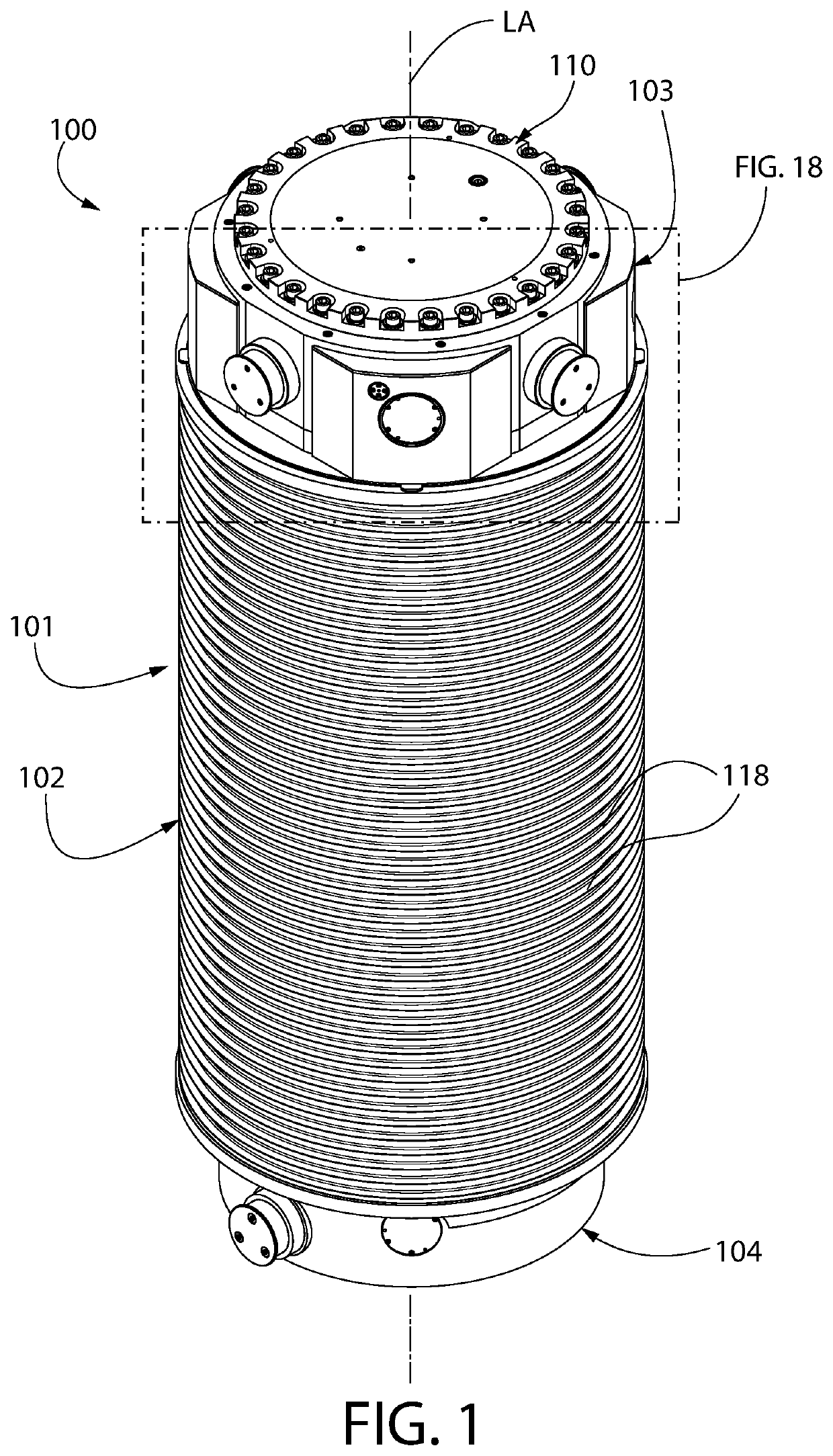
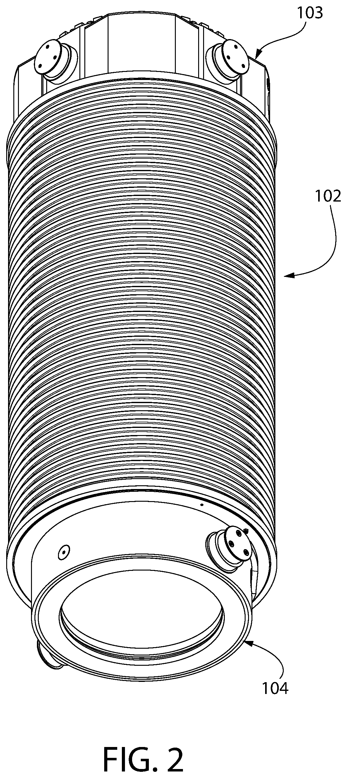
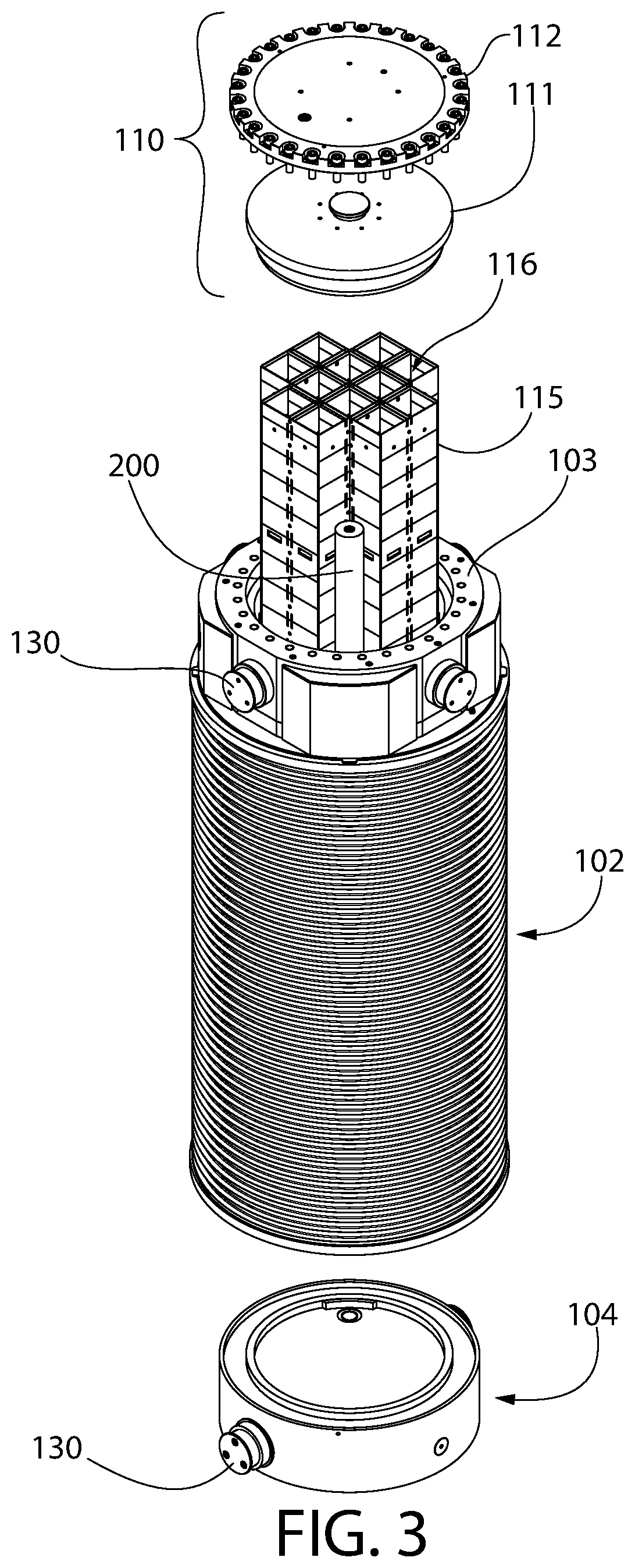
A radioactive nuclear waste storage system includes a cask comprising a hermetically sealed internal cavity configured for holding the waste such as spent nuclear fuel submerged in an inventory of water. One or more pressure surge capacitors disposed inside the cask include a vacuum cavity evacuated to sub-atmospheric conditions prior to storage of fuel in the cask. At least one rupture disk seals a vacuum chamber inside each capacitor. Each rupture disk is designed and constructed to burst at a predetermined burst pressure level occurring inside the cask external to the capacitor. This allows excess cask pressure occurring during a high pressure excursion resulting from abnormal operating conditions to bleed into capacitor, thereby returning the pressure inside the cask to acceptable levels. In one embodiment, the capacitors are located in peripheral regions of the cask cavity adjacent to the circumferential wall of the cask body.

Description

CROSS-REFERENCE TO RELATED APPLICATIONS[0001]This application claims the benefit of U.S. Provisional Application No. 63 / 003,431 filed Apr. 1, 2020, which is incorporated herein by reference in its entirety.BACKGROUND[0002]The present invention relates generally to systems and vessels for storing and transporting high level radioactive nuclear waste such as used or spent nuclear fuel (SNF), and more particularly to a wet cask storage system with overpressurization protection.[0003]A typical module or cask employed to store and transport fissile radioactive waste such as SNF uses an inert gas such as helium to protect the elongated zirconia metal tubes (also referred to as tube cladding) of the fuel rods from oxidation. Such casks insert gas filled casks are referred to as a “dry cask.” Multiple fuel rods are bundled together in a support structure referred to as a fuel assembly which are well known in the art without undue elaboration here. The fuel assemblies are liftable structures...

Claims


Application Information

Patent Timeline
IPC IPC(8): G21F5/12G21F5/012
CPCG21F5/12G21F5/012G21F5/10G21F5/06Y02E30/30G21C19/32
Inventor SINGH, KRISHNA P.GRIFFITHS, JOHN D.
Owner HOLTEC INT
Learn More