
Electric drive

a technology of electric drive and electric drive unit, which is applied in the direction of electric propulsion mounting, magnetic circuit shape/form/construction, magnetic circuit rotating parts, etc., can solve the problems of reducing affecting the efficiency of electric drive, so as to reduce the weight of a disclosed drive unit and increase the performance of electric drive.

Active Publication Date: 2021-11-11
VOLVO CAR CORP
View PDF4 Cites 0 Cited by
  • Summary
  • Abstract
  • Description
  • Claims
  • Application Information

AI Technical Summary

Benefits of technology

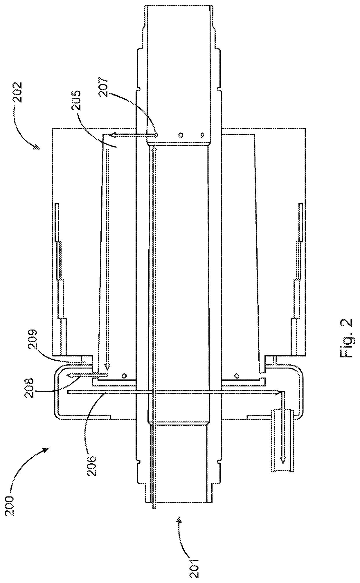
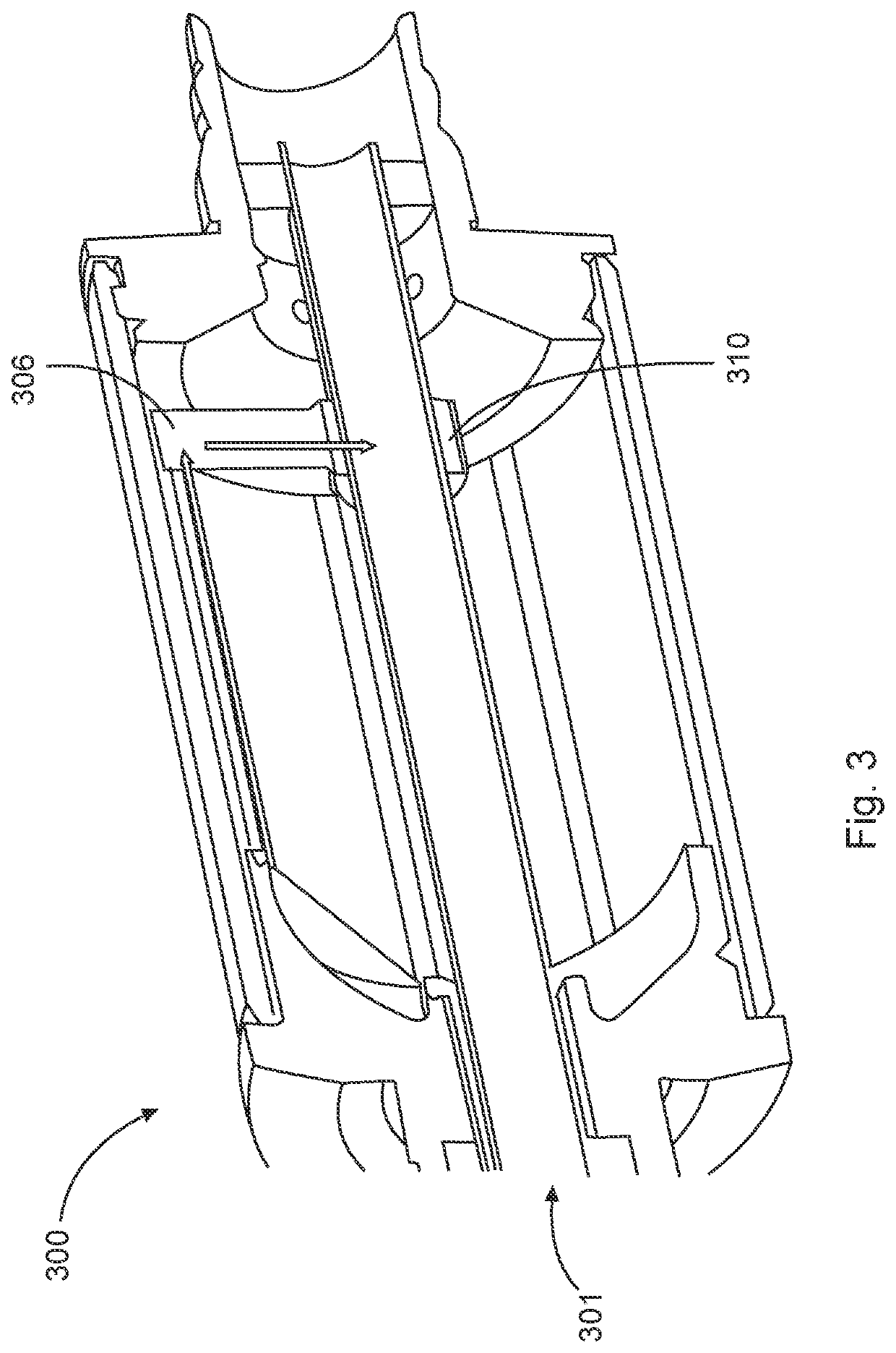
The present disclosure proposes a coolant circuit for an electric drive that includes a cooling section adjacent to the rotor unit. The cooling section extends along the axis of rotation of the rotor unit and has a radius that increases along the direction of rotation. This allows the coolant to flow through the cooling section without the need for a separate pump. The coolant can be transported to the cooling section with the rotation of the rotor unit, and the coolant flows through the cooling section due to the rotation. This coolant circuit can improve the performance of the electric drive without adding weight or complexity. The cooling section can be designed as a circulating chamber or a straight-line bore. The inflow and discharge sections can be provided by bores in the hollow shaft or from the cooling section to the hollow shaft. The coolant circuit can be used without a separate pump, reducing the weight of the drive unit.

Problems solved by technology

However, such a temperature increase has a negative effect on the efficiency of the electric drive reducing the performance of the electric drive.

Method used


Image

  • Electric drive
  • Electric drive
  • Electric drive

Examples


Embodiment Construction

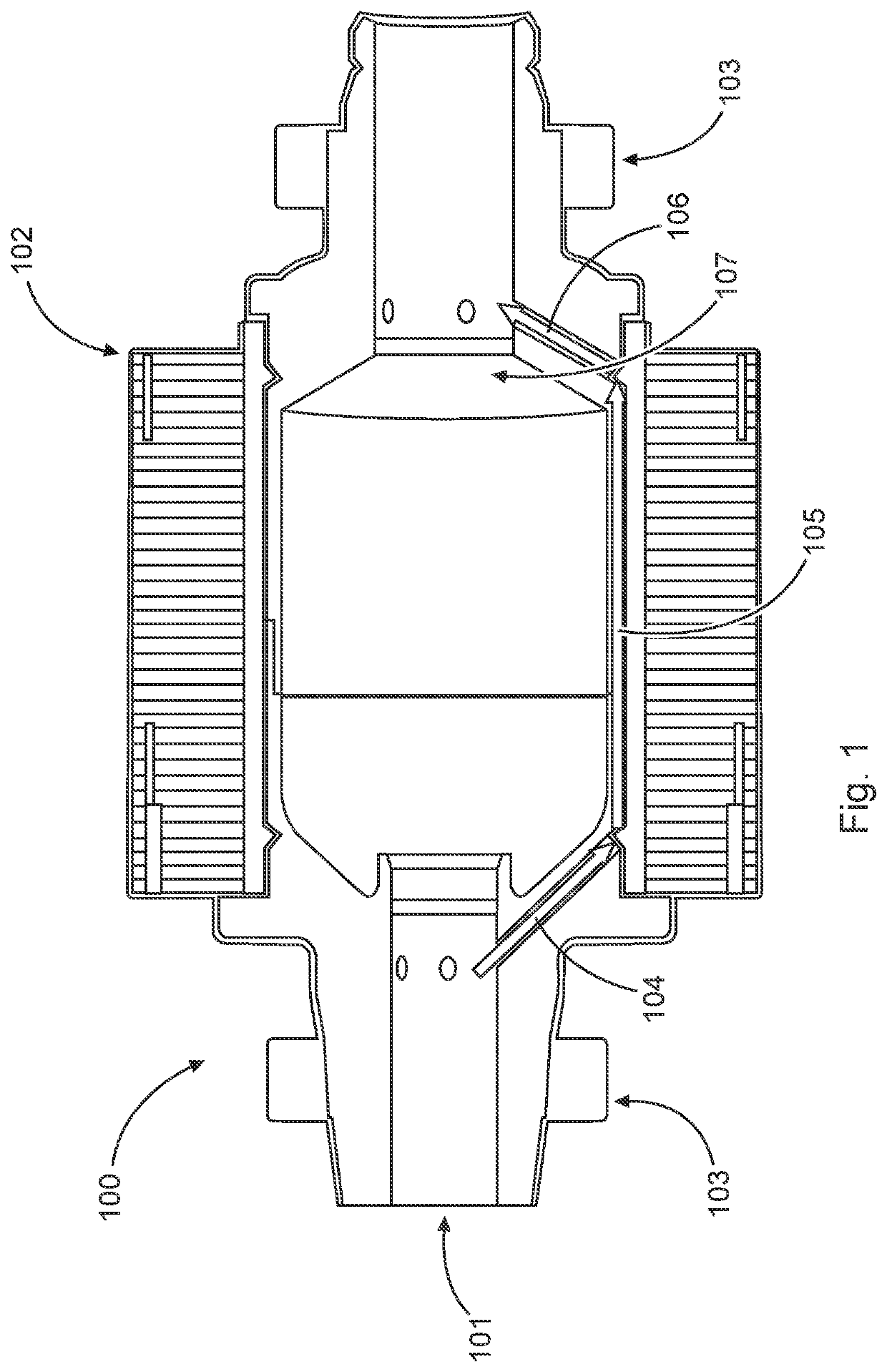
[0026]FIG. 1 is a schematic view of a drive unit 100 according to an embodiment of the present disclosure. The drive unit 100 comprises hollow shaft 101 mounted for rotation about an axis of rotation, a rotor unit 102, which is arranged rotationally fixed with the hollow shaft 101, i.e. when the rotor unit 102 is driven by a stator unit (not shown), the rotor unit 101 and thus the hollow shaft 101 are rotated. The drive unit 100 or the rotor unit 102 may be rotatably connected with the stator unit by means of corresponding bearing assemblies 103.

[0027]The drive unit 100 further comprises a coolant circuit comprising at least an inflow section 104, a cooling section 105 and a discharge section 106. In FIG. 1, the path of the coolant through the inflow section 104, the cooling section 105 and the discharge section 106 is indicated by arrows.

[0028]The function of the inflow section 104 is to conduct the coolant, e.g. oil, to the cooling section 105, whereby the geometry of the inflow s...


PUM


Abstract

Electric drive (100, 200, 300, 400) for a vehicle, comprising: at least one hollow shaft (101, 201, 301, 401) mounted for rotation about an axis of rotation; at least one rotor unit (102, 202) being arranged rotationally fixed with the hollow shaft (101, 201, 301, 401); at least one coolant circuit being provided at least partially between the hollow shaft (101, 201, 301, 401) and the rotor unit (102, 202); the coolant circuit comprising at least one cooling section (105, 205) being provided adjacent to the rotor unit (102, 202); and wherein the cooling section (105, 205) has an increasing radius at least partially along its extension parallel to the axis of rotation.

Description

CROSS-REFERENCE TO RELATED APPLICATIONS[0001]This application claims the benefit of priority to EP Patent Application No. 20172926.6 filed May 5, 2020 entitled “ELECTRIC DRIVE.” The entirety of the aforementioned application is hereby incorporated herein by reference.TECHNICAL FIELD[0002]The present disclosure relates to an electric drive for a vehicle, a use of such an electric drive in a vehicle and a vehicle comprising such an electric drive.BACKGROUND ART[0003]In the prior art, electric drives / electric machines are known in a variety of different designs. For example, synchronous motors are known comprising a rotor unit in which permanent magnets are arranged. These permanent magnets can be driven by magnetic interaction provided by a stator unit arranged around the rotor unit. Thereby, the rotor unit may be set in rotation.[0004]During the use of an electric drive, the rotor unit and in particular the magnets of the rotor unit can become warmer. However, such a temperature incr...

Claims


Application Information

Patent Timeline
Patent Type & Authority Applications(United States)
IPC IPC(8): B60K11/02B60K1/00H02K5/20H02K7/00H02K9/19
CPCB60K11/02B60K1/00B60K2001/006H02K7/003H02K9/19H02K5/203H02K1/32
Inventor EHN, JOAKIMSANDSTRÖM, HÅKAN
Owner VOLVO CAR CORP
Learn More