Electro-pneumatic pressure control module implemented as a component and having an integrated inertial sensor

Pending Publication Date: 2021-11-18
KNORR-BREMSE SYST FUER NUTZFAHRZEUGE GMBH
View PDF0 Cites 0 Cited by
  • Summary
  • Abstract
  • Description
  • Claims
  • Application Information

AI Technical Summary

Benefits of technology

[0005]The present invention is therefore based on an object of refining a pressure control module such that an electro-pneumatic service brake installation of a vehicle that has such a pressure control module has a simpler and more robust construction and

Problems solved by technology

However, in such inertia sensors, oscillations and vibrations which emanate from switching procedures of solenoid valves of the pressure control modules can lead to measurement errors when the oscillati

Method used


Image

  • Electro-pneumatic pressure control module implemented as a component and having an integrated inertial sensor
  • Electro-pneumatic pressure control module implemented as a component and having an integrated inertial sensor
  • Electro-pneumatic pressure control module implemented as a component and having an integrated inertial sensor

Examples


Embodiment Construction

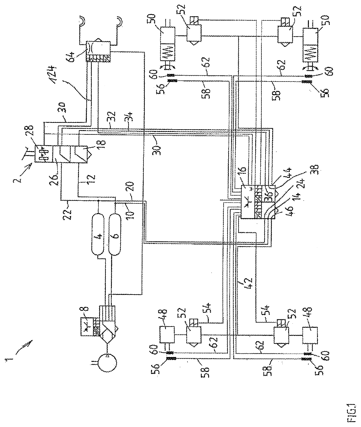
[0117]FIG. 1 shows a circuit diagram of an electro-pneumatic service brake installation 1, for example of a heavy commercial vehicle, having a foot brake value valve or a foot brake module 2, a first (front axle) reservoir pressure vessel 4 for supplying a first (front axle) pressure control channel 9, and a second (rear axle) reservoir pressure vessel 6 for supplying a second (rear axle) pressure control channel 11.

[0118]The provision of air, the treatment of air, and the safety measures here are embodied as prescribed by legislation by way of an air treatment module 8 which is not described in more detail here.

[0119]The second (rear axle) reservoir pressure vessel 6 by way of pneumatic supply lines 10, 12 is connected to a second (rear axle) reservoir connector 14 of a central, for example dual-channel, pressure control module 16, on the one hand, as well as to a second (rear axle) channel 26 of the foot brake valve 2.

[0120]In an analogous manner, the first (front axle) reservoir ...


PUM


Abstract

An electro-pneumatic central pressure control module having at least a single channel, and which is implemented as a component for an electro-pneumatic service brake of a vehicle, having at least one pressure control channel which is electrically controllable with regard to a brake pressure. Also described is an electronic control device of the pressure control module having a board carrying electrical and electronic components, at least one inertial sensor being arranged on or at the at least one board and being electrically conductively connected to at least several of the electrical and electronic components on the board, in which an arrangement/apparatus ensures a lower vibration load of the inertial sensor on the board.

Description

FIELD OF THE INVENTION[0001]The invention proceeds from an at least 1-channel electro-pneumatic pressure control module embodied as a functional unit for an electro-pneumatic service brake installation of a vehicle, having at least one pressure control channel which is electrically controllable in terms of a first service brake pressure.BACKGROUND INFORMATION[0002]An electro-pneumatic service brake installation of a vehicle is discussed in EP 1 122 142 A1 and has a 2-channel pressure control module for the rear axle, wherein one channel supplies in each case one wheel brake of the rear axle with a brake or operating pressure. In contrast, the wheel brake cylinders of the front axle are in each case aerated or vented, respectively, by a dedicated 1-channel pressure control module. These 1-channel pressure control modules moreover have a respective purely pneumatic backup circuit so as to, in the event of a failure of the electrics, still be able to brake on account of the pressure th...

Claims


Application Information

Patent Timeline
IPC IPC(8): B60T13/68B60T8/32B60T13/26B60T8/171B60T17/22B60T15/02B60T8/94B60T8/17B60T8/176B60T7/12
CPCB60T13/683B60T2260/08B60T13/268B60T8/171B60T17/221B60T15/027B60T8/94B60T8/1701B60T8/176B60T7/12B60T2270/88B60T2270/82B60T2270/30B60T2270/10B60T2270/20B60T2270/402B60T2270/404B60T8/327B60T8/3675B60T8/3605B60T8/361B60T13/26B60T13/662
Inventor EISENBERGER, ANDREASHERGES, MICHAELHUBER, CHRISTOPHSTEINBERGER, JUERGEN
Owner KNORR-BREMSE SYST FUER NUTZFAHRZEUGE GMBH
Why Eureka
Try Eureka