Laser welding method

Active Publication Date: 2021-11-25
COHERENT INC
View PDF0 Cites 4 Cited by
  • Summary
  • Abstract
  • Description
  • Claims
  • Application Information

AI Technical Summary

Benefits of technology

The present invention provides a method for laser welding a workpiece along a weld line using a focused beam of laser radiation. The focused beam has a focused center beam and a concentric focused annular beam. The focused center beam is smaller than the focused annular beam on a surface of the workpiece exposed to the focused beam. The focused beam is moved laterally with respect to the workpiece along the weld line. The power of the annular beam is reduced from the annular processing power. The lateral movement of the focused beam with respect to the workpiece is stopped when the focused beam reaches an end location on the weld line. The power of the center beam is increased from the center processing power. The power of the annular beam is ramped down at a first annular ramp rate while the power of the center beam is ramped down at a first center ramp rate. The second annular ramp rate is less than the first annular ramp rate. The second center ramp rate is less than the first center ramp rate. This method ensures a high-quality weld along the weld line with reduced power consumption and improved efficiency.

Problems solved by technology

Traditional mechanical processing produces unwanted defects, such as micro-cracks that may propagate when a processed workpiece is stressed, thereby degrading and weakening the processed workpiece.
However, it can be difficult to maintain a stable keyhole in a hot and dynamic pool of melted material.
One problem when laser welding some metals and metal alloys is the formation of defects, particularly cracks, at the termination of a line weld.
Some defects are caused by stress that is induced while the workpiece is cooling.
These initial defects weaken a welded workpiece and may further propagate if thermal or mechanical stress is applied when the finished workpiece is put to use.
An unreliable weld in a structure could lead to catastrophic failure.
Although these solutions have been successful for many materials, they have proven insufficient for modern high-strength metal alloys with relatively high thermal conductivity.
These materials remain stubbornly prone to cracking at the beginning of a laser weld and, particularly, at the termination of a laser weld.
While this method works well to prevent defects, the focused laser beam is moving across the surface of the workpiece during these power changes, producing a gradual taper in the width of the weld.
This taper is typically a few millimeters long and is unacceptable in some applications that require a uniform cross section along the whole length of the weld.

Method used


Image

  • Laser welding method
  • Laser welding method
  • Laser welding method

Examples


Embodiment Construction

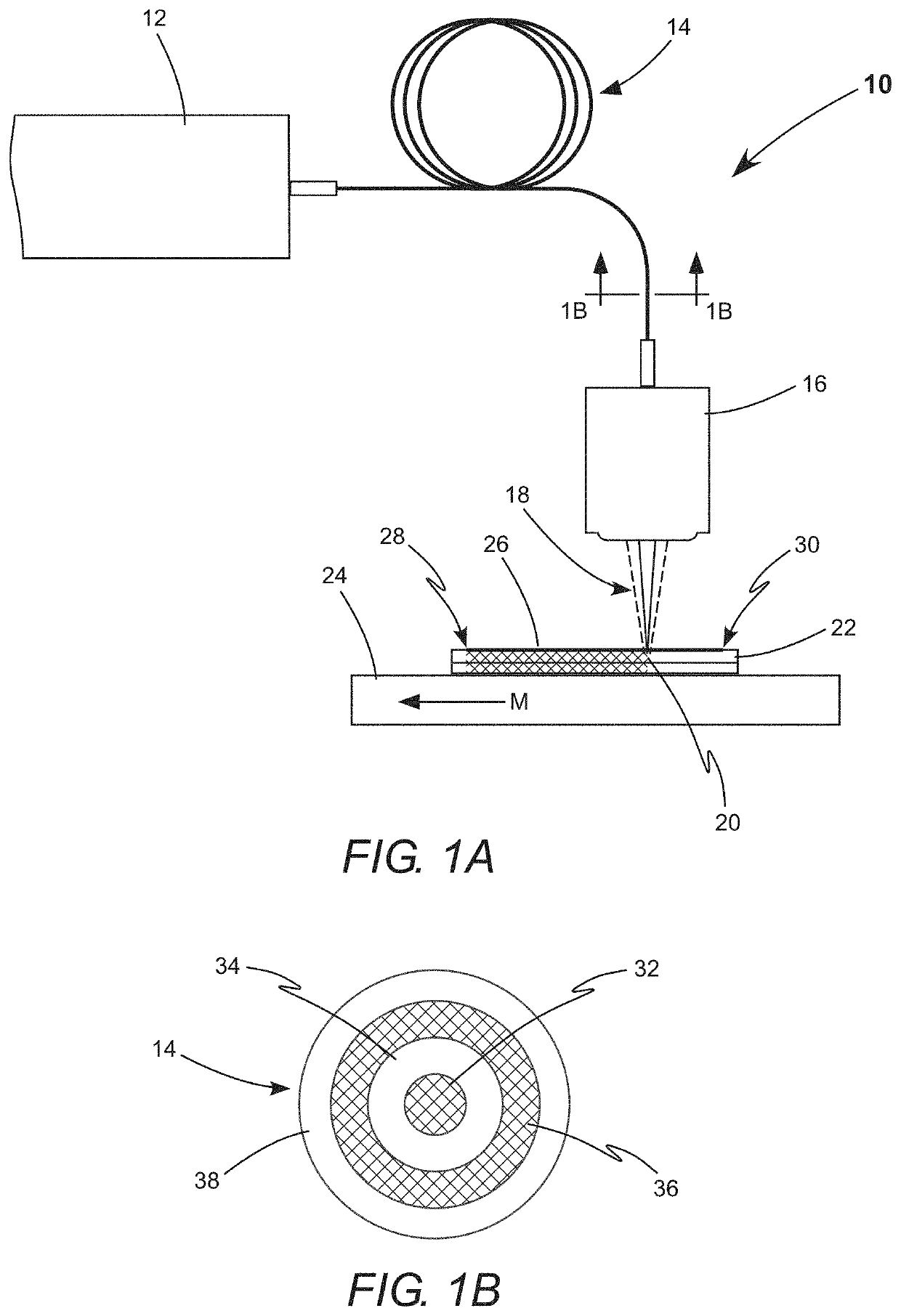
[0020]Referring now to the drawings, wherein like components are designated by like numerals, FIGS. 1A and 1B schematically illustrate an apparatus 10 used in prior-art laser processing methods and in the laser welding method of the present invention. A laser source 12 delivers at least two beams of laser radiation through an optical fiber 14 to a focusing lens 16. Optical fiber 14 includes a center core 32 for guiding a center beam of laser radiation. Center core 32 has a low refractive index cladding 34. Optical fiber 14 further includes an annular core 36 for guiding an annular beam of laser radiation. Annular core 36 is concentrically located between low refractive index cladding 34 and another low refractive index cladding 38. Laser source 12 is configured to deliver the center beam to center core 32 and the annular beam to annular core 36. Laser systems integrating such a laser source with such an optical fiber are commercially available. For example, the Highlight™ FL-ARM las...


PUM

PropertyMeasurementUnit
Poweraaaaaaaaaa
Fractionaaaaaaaaaa
Fractionaaaaaaaaaa

Abstract

A method for laser keyhole welding is disclosed to weld two pieces together made of a metal alloy. The method independently adjusts power in a focused center beam and power in a concentric focused annular beam. At the termination of a weld, the power of the annular beam is reduced, motion of the focused beams is stopped, the power of the center beam is increased, and the power of both beams is initially ramped down rapidly and then ramped down slowly. Increasing the power of the center beam equalizes the temperature of both pieces prior to solidification and cooling at the termination of the weld. An additional pulse of power may be applied to prevent the formation of defects or to erase any defects.

Description

TECHNICAL FIELD OF THE INVENTION[0001]The present invention relates in general to welding using focused beams of laser radiation. The invention relates in particular to welding metal alloys using a focused center beam and a focused annular beam.DISCUSSION OF BACKGROUND ART[0002]Beams of laser radiation are increasingly used for cutting, drilling, welding, marking, and scribing workpieces made of a wide range of materials; including metals and metal alloys. Traditional mechanical processing produces unwanted defects, such as micro-cracks that may propagate when a processed workpiece is stressed, thereby degrading and weakening the processed workpiece. Laser processing minimizes such unwanted defects, is generally cleaner, and causes a smaller heat-affected zone. Laser machining uses a focused laser beam to produce precise cuts and holes, having high-quality edges and walls, while minimizing the formation of unwanted defects.[0003]In laser welding, a focused laser beam locates each we...

Claims


Application Information

Patent Timeline
IPC IPC(8): B23K26/244B23K26/073B23K26/06B23K26/0622
CPCB23K26/244B23K26/0734B23K2103/04B23K26/0622B23K26/0648B23K26/0613B23K26/0626B23K26/0665
Inventor BRESCOE, RYAN
Owner COHERENT INC
Why Eureka
Try Eureka