Dead-time control method for power electronics converters and a circuit for the application of this method

a power electronics converter and control method technology, applied in the direction of ac-dc conversion, power conversion systems, electrical apparatus, etc., can solve the problems of increasing the cost of use of many components, and affecting the operation of power electronics converters. achieve the effect of easy implementation of digital or analog circuits

Active Publication Date: 2021-12-02
YILDIZ TEKNIK UNIVSI
View PDF2 Cites 0 Cited by
  • Summary
  • Abstract
  • Description
  • Claims
  • Application Information

AI Technical Summary

Benefits of technology

[0003]Dead time is set between the signals to prevent short-circuit of the elements in the phase arm in inverters. The dead time, which must be set between the drive signals of the semiconductor power switches, leads to disturbances in current and voltage control. Dead time compensation methods have been developed to prevent this degradation. Dead time compensation in PWM methods has been extensively discussed in literature and patents. Dead time compensation stands out in inverter applications and improves the quality of the output voltage and current. The dead time set between the drive signals of the upper and lower switches in a phase arm causes the inverter output voltage to be different than the desired value according to the polarity of the current. In order to prevent this, the load ratio according to the polarity of the current, is increased or decreased in the amount of dead time in the PWM generation stage.
[0005]In the context of hysteresis current control, studies have been carried out in the literature to keep the switching frequency constant and solve the dead time problem. These studies were compared with the invention proposal and no direct similarity was determined. In [47], an estimation-based method has been developed to formulate the switching function with current reference, dynamic behavior and past time information of the system. The method comprises a very complex hardware. Calculation is done with analog circuit. The use of many components increases the cost and makes the applicability difficult and decrease the reliability. In [48], a numerical control method is presented to keep the frequency constant in hysteresis current control. The method is adaptive to the load parameters and the input source. The dead time effect is compensated by the PI controller. In [49]-[51], a numerical method that automatically compensates the dead time effect is used. In [52] and [53], a study was carried out for single-phase three-level inverters. In [52], a method independent from the load parameters is proposed. This method obtains appropriate switching signals according to the upper / lower hysteresis bandwidth, current error and switching state, to eliminate the dead time effect without dead time compensation. In [53], two techniques are presented to stabilize the frequency at the zero crossing points of the grid. These techniques are mixed-level model and estimation-based sampling. In the mixed-level model, a transition from three-level state to two-level state is made around zero. Estimation-based sampling aims to achieve the most effective switching. In [54], the effect of change in the switching frequency and sampling frequency in the hysteresis band is analyzed. The difference between the maximum and minimum switching frequency of the fixed band hysteresis current control depends on the sampling frequency of the digital controller. But in here the dead time is neglected. In addition, there are some studies for three-phase systems [55], [56]. In [55], a space vector-based approach is presented. In [56], the average inverter output voltage is used as an approach to the back-emf value of the load for constant frequency hysteresis current control. In here the dead time delay is calculated and compensated by taking this delay into account.
[0103]Thanks to the developed dead time method, problems of overflow of the current due to dead time and inability to keep the frequency constant are largely solved. The developed method is very simple and can be easily implemented with digital or analog circuits.

Problems solved by technology

The dead time, which must be set between the drive signals of the semiconductor power switches, leads to disturbances in current and voltage control.
The method comprises a very complex hardware.
The use of many components increases the cost and makes the applicability difficult and decrease the reliability.
But in here the dead time is neglected.
Dead time has adverse effects on hysteresis current control method.
This is due to the fact that the driving signal cannot be applied immediately when the current goes out of the hysteresis band and that the current continues to travel in the same direction as much as the dead time, especially in areas where the current changes rapidly.
However, due to dead time, the current exceeds the calculated band and the frequency cannot be kept constant.
According to this, frequency control is seriously deteriorating.

Method used


Image

  • Dead-time control method for power electronics converters and a circuit for the application of this method
  • Dead-time control method for power electronics converters and a circuit for the application of this method
  • Dead-time control method for power electronics converters and a circuit for the application of this method

Examples


Embodiment Construction

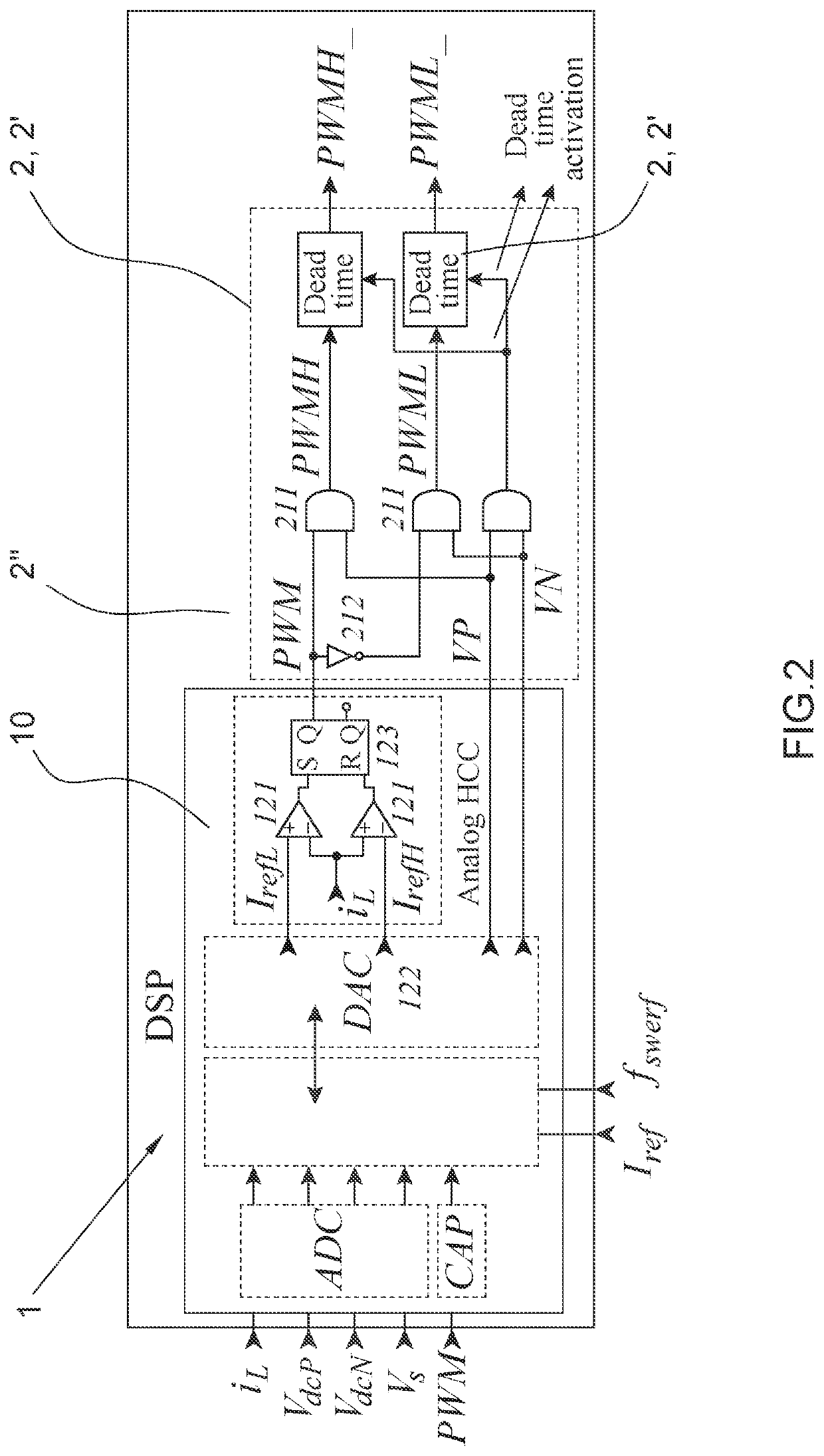
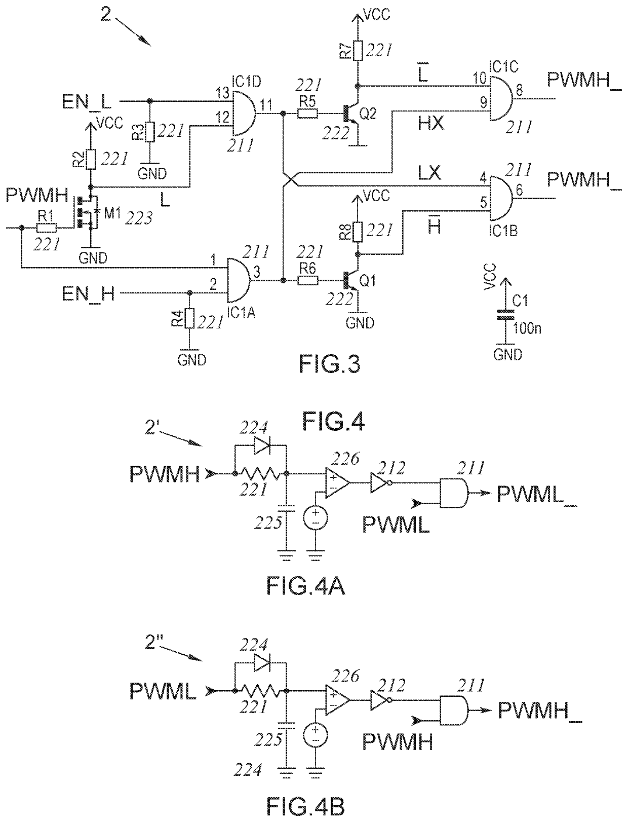
[0147]An invention circuit (1) and a dead time control circuit (2 or 2′) are used in the method according to the invention. PWM, PWMH, PWML and EN_L, EN_H signals, which are going to be used at the input of the dead time circuit (2 or 2′), are generated with the invention circuit (1). On the other hand, PWMH_ and PWML signals, which are going to be applied to power electronics converters, for example to a two level voltage sourced inverter, are generated in the dead time circuit (2 or 2′).

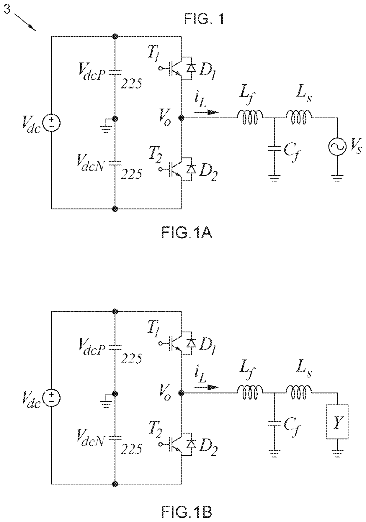
[0148]Application circuit (3) comprises a diode (D1) to which an upper switch (T1) is parallel connected and a diode (D2) to which a lower switch (T2) is parallel connected. At the output of the application circuit (3). which is a two level half bridge inverter topology, grid voltage (Vs) and filter components (Lf, Cf, Ls) as to be filter inductance of inverter output (Lf), filter capacitor (Cf) and filter inductance of the grid (Ls) are provided. Ground of the grid voltage (Vs) is connected to the...


PUM


Abstract

A dead time control method (100) comprising the steps of: converting the DC link voltage, output current and output voltage to digital values with an ADC (Analog to Digital converter) (102); calculating the hysteresis band for adaptive hysteresis current control using the values read by the ADC and updating the band value via recalculating it at each sampling time (103); calculating the IrefH and IrefL values using the hysteresis band and Iref (103a); generating the PWM signal by hysteresis current control (104), generating two auxiliary control signals as VP, VN (105); in the region where VP=1 and VN=0, applying of the drive signal of T1 without setting dead time wherein T1 is the conduction duration of an upper switch, and not applying the drive signal of T2 wherein T2 is the turn off duration of said upper switch and is the conduction duration of a lower switch (106).

Description

TECHNICAL FIELD[0001]This invention relates to a dead time control method for use in power electronics converters and to a circuit developed for implementation of this method.PRIOR ARTBrief Description of the Problem[0002]Hysteresis current control or PWM (pulse width modulation) methods are used for current control in inverters. In the hysteresis current control method, the inverter current is controlled such that it remains in the upper and lower band defined around the reference current. Dead time is set between the signals to prevent short-circuit of the elements in the phase arm in inverters. Due to the dead time set, the current extends beyond the hysteresis band. In this case, the current control is disrupted.Prior Art Practices[0003]Dead time is set between the signals to prevent short-circuit of the elements in the phase arm in inverters. The dead time, which must be set between the drive signals of the semiconductor power switches, leads to disturbances in current and volt...

Claims


Application Information

Patent Timeline
Patent Type & Authority Applications(United States)
IPC IPC(8): H02M7/5387H02M1/38H02M1/00H02M1/32H02M1/12
CPCH02M7/53873H02M1/385H02M1/126H02M1/32H02M1/123H02M1/0012H02M1/38H02M7/5387
Inventor BAKAN, AHMET FARUKDUDAK, AHMET TALHA
Owner YILDIZ TEKNIK UNIVSI
Why Eureka
Try Eureka