
Methods and system for estimating a temperature of an after treatment device

Active Publication Date: 2021-12-16
FORD GLOBAL TECH LLC
View PDF2 Cites 2 Cited by
  • Summary
  • Abstract
  • Description
  • Claims
  • Application Information

AI Technical Summary

Benefits of technology

The patent describes a method for controlling the temperature of an after treatment device in a vehicle engine. This is important because the device oxidizes and reduces exhaust gas constituents and the temperature affects its efficiency. By estimating the temperature and reducing the amount of hydrocarbons in the exhaust gases, the after treatment device can be maintained at a high efficiency. This approach also reduces the amount of fuel vapor stored in the fuel vapor canister and improves the accuracy of temperature estimates.

Problems solved by technology

Operating the after treatment device at temperatures that are higher than a threshold temperature may result in a loss of after treatment device efficiency.
Nevertheless, installing temperature sensors in the after treatment device may be cost prohibitive.

Method used


Image

  • Methods and system for estimating a temperature of an after treatment device
  • Methods and system for estimating a temperature of an after treatment device
  • Methods and system for estimating a temperature of an after treatment device

Examples


Embodiment Construction

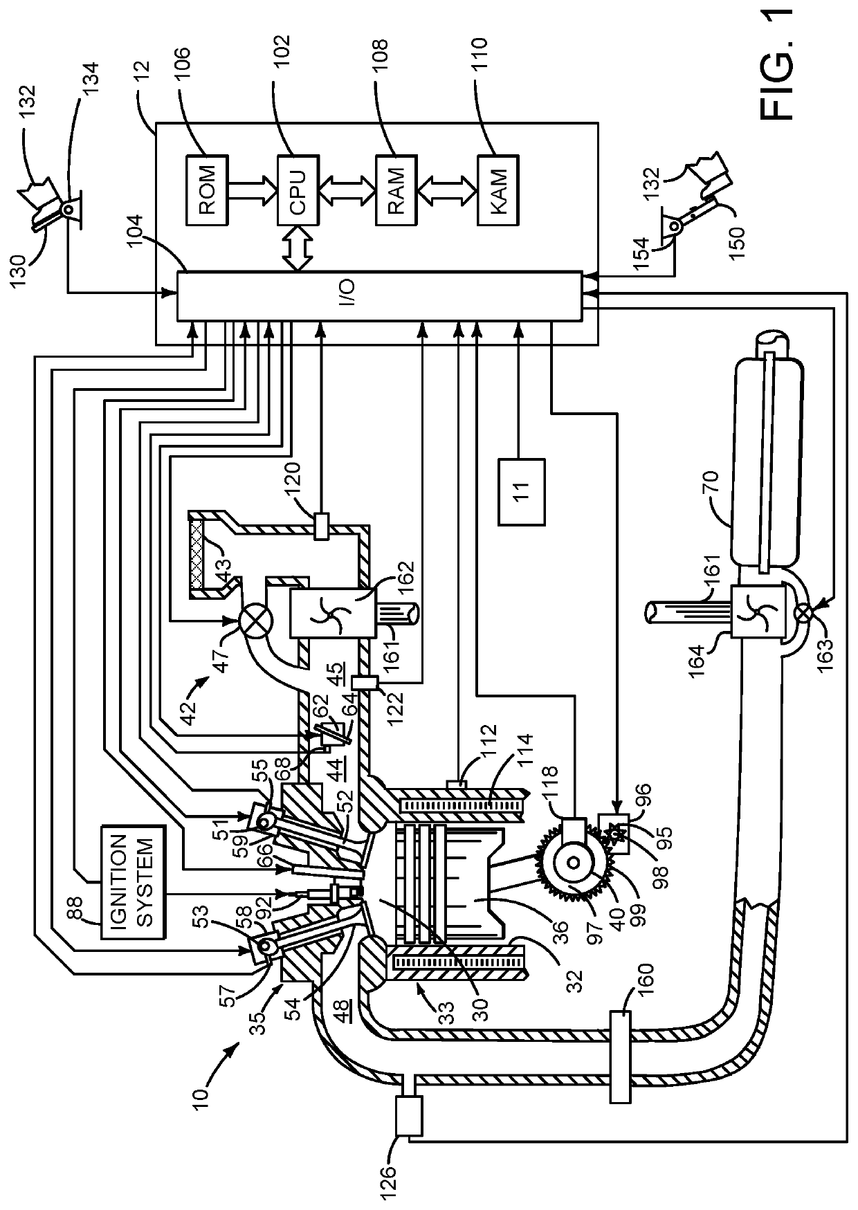
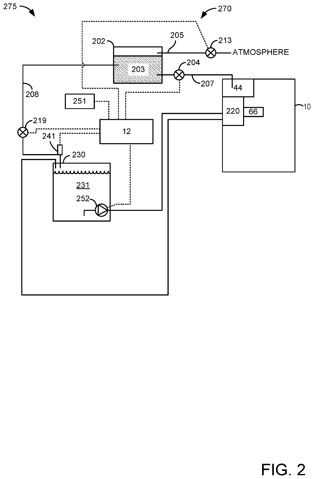
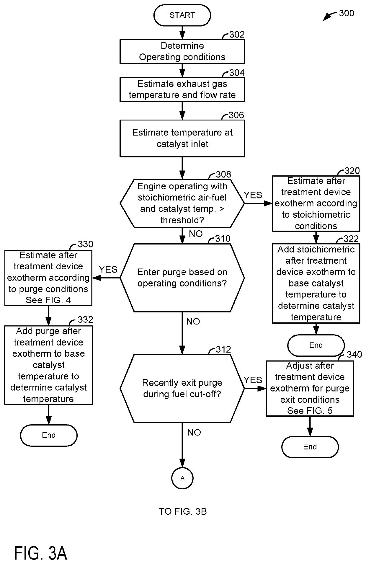
[0015]The present description is related to estimating a temperature of an exhaust after treatment device. The temperature of the exhaust after treatment device may be determined when purge fuel vapors are flowing to an engine operating in a fuel cut-out mode and when the after treatment device is being reactivated after exiting fuel cut-out mode. The engine may be of the type shown in FIG. 1. The engine may periodically receive fuel vapors from an evaporative emissions system as shown in FIG. 2. A method for estimating a temperature of an after treatment device and operating an engine is shown in FIGS. 3A-3C. An example engine operating sequence in which a temperature of an exhaust after treatment device is estimated while the engine operates in fuel cut-out mode is shown in FIG. 4. Another example engine operating sequence is shown in FIG. 5 where a temperature of the exhaust after treatment device is estimated while the exhaust after treatment is being reactivated. A graphic depi...


PUM


Abstract

Systems and methods for estimating a temperature of an after treatment device in an exhaust system of an engine are described. In one example, the temperature is estimated during condition when an engine is in a fuel cut-out mode and fuel vapors are being released to the engine via a fuel vapor storage canister.

Description

FIELD[0001]The present description relates to methods and a system for estimating a temperature of an after treatment device and adjusting operation of a vehicle responsive to the temperature. The methods and systems may be particularly useful for vehicles that may include a fuel vapor collection and purging system.BACKGROUND AND SUMMARY[0002]A vehicle may include an after treatment device for processing exhaust gases of an engine. The after treatment device may oxidize some exhaust gas constituents and reduce other exhaust gas constituents. The after treatment device may be initially heated via exhaust gases. Once it reaches a light off temperature, the after treatment device may reach temperatures that may be higher than exhaust gas temperatures. In particular, hydrocarbons entrained in the exhaust gases may be combusted within the after treatment device so as to raise a temperature of the after treatment device. The temperature of the after treatment device may be increased or de...

Claims


Application Information

Patent Timeline
IPC IPC(8): F02D41/00F02D41/30F02M25/08F02D41/02
CPCF02D41/004F02D41/3017F02D2200/0804F02M25/0836F02D41/0235F02M25/0854F02D41/123F02D41/38F01N11/005F01N9/00F02D2041/389Y02T10/40F02D2200/0802F02D41/0087F02D41/0045F02D41/0032F02D41/029F01N3/20
Inventor LEHMEN, ALLENVAN NIEUWSTADT, MICHIEL J.BEHR, KENNETH JOHNBUCKROP, DANIELSANBORN, ETHAN D.FRIED, MARCUS WILLIAM
Owner FORD GLOBAL TECH LLC
Learn More