Measurement and imaging instruments and beamforming method

a measurement and imaging technology, applied in the field of measurement and imaging methods, can solve the problems of insufficient sampling frequency of ad converters, insufficient measurement accuracy, and insufficient spatial resolution of signals, and achieve the effects of increasing measurement accuracy, reducing measurement accuracy, and increasing measurement accuracy

Pending Publication Date: 2021-12-16
SUMI CHIKAYOSHI
View PDF0 Cites 1 Cited by
  • Summary
  • Abstract
  • Description
  • Claims
  • Application Information

AI Technical Summary

Benefits of technology

[0122]According to some aspect of the present invention, overcome can be the problem of the usual demodulation method (patent documents 7 and 8), for a displacement vector observation with a 2D or 3D lateral modulations, that the measurement accuracy decreases in a practice since the waves do not become symmetric strictly in a practice even if waves are generated to be symmetrically crossed by steerings (beamforming) with respect to the axes of an axial direction or the lateral direction orthogonal to the axial direction of the orthogonal coordinate system to be used for the observation (i.e., axial and lateral axes, respectively) and areas including the axial axis and the lateral direction orthogonal to the axial axis (i.e., All waves are to be symmetric with respect to the axial direction). That is, the measurement accuracy increases much. Moreover, overcome can also be the problem that it becomes impossible to perform the observations when performing the steering the central axis of the steered waves from the frontal direction of the aperture. That is, various beamformings can be used for the displacement vector measurement with the demodulation processing. Furthermore, overcome can also be the problem that a measurement error also occurs when the instantaneous frequencies or the local spectral 1st moments (center frequencies) in the propagation directions of generated, steered waves (i.e., the waves themselves' frequencies) differ each other. The measurement accuracy increases.
[0123]In addition, according to some aspect of the present invention, by performing new Hilbert transforms using the (partial) differential processing or the (fast) Fourier transform, it becomes possible to perform various applications with a high speed such as the imaging of waves, the displacement (vector) measurement, the temperature measurement, etc. (The former is faster than the latter). When generating plural beams or waves with different wave parameters such as an ultrasound, etc. or beamforming parameters at every temporal phase, since the number of performing beamformings and Hilbert transforms due to increasing the reception signals received by the reception transducer, the new Hilbert transforms are effective. The new Hilbert transforms are also effective when a beamforming is performed at once for a superposition of reception echo signals received by the reception transducer. The high speediness of new Hilbert transforms becomes further effective in a case where the physical aperture element comprises a 2D or 3D distribution or a multi-dimensional array since the new transforms efficiently overcomes the problem that much longer processing time is required.
[0124]In addition, it is made possible, by using a fast Fourier transform while using instruments with digital operational functions as digital beamformers, to perform arbitrary beamformings with high speeds and high accuracies with no approximate calculations (Fourier beamforming). As explained later in detail, the present invention realizes, on the basis of proper using of the multiplications of complex exponential functions and the Jacobi operation, arbitrary beamformings on arbitrary orthogonal coordinate systems including a curvilinear coordinate system with high speeds and high accuracies with no approximate interpolations. When generating plural beams or waves with different wave parameters such as an ultrasound, etc. or beamforming parameters, a beamforming can be performed at once for a superposition of reception echo signals received by a reception transducer.
[0125]Although the DAS (Delay and Summation) processing also realizes arbitrary beamformings including conventional beamformings, when using a 1D array-type physical aperture and a general PC (personal computer), at least the present invention makes the calculation speeds 100 times as high as those achieved using the DAS processing. When the aperture elements distribute in a 2D or 3D space or comprise a multi-dimensional array, the present invention efficiently solve the problem that it takes more processing times in the multi-dimensional cases than in the 1D case, i.e., the increasing the speediness of beamforming becomes more efficient. Off course, the DAS processing can also be used.
[0126]That is, the present invention uses a transmission or reception transducer array device with an arbitrary aperture geometry (it may be used for both transmission and reception) or a sensor array device, and allows arbitrary beamformings with high speeds and high accuracies and with no approximate interpolations via digital processing. In practical, arbitrary focusings, arbitrary steerings, arbitrary apodizations can be performed with array devices with arbitrary aperture geometries.
[0127]For instance, in a field of medical ultrasound imaging, according to observation targets, a coordinate system on which physical transmission and reception and digital sampling are performed is selected such as a Cartesian coordinate system for a linear array-type transducer and a polar coordinate system popular for a convex type transducer, a sector scan, or an IVUS (intravascular ultrasound). For instance, for observing heart dynamics between ribs, the sector scan is performed generally. An aperture of not a transducer with an array-type aperture geometry but a PVFD (polyvinylidene fluoride) based transducer may be deformable. That is, the present invention allows obtaining signals directly beamformed on arbitrary coordinate systems such as image displays, etc. with no approximate interpolations by processing digital signals obtained from waves transmitted and received on arbitrary coordinate systems. Composite transducer comprising of PVDF that allows generating a high frequency ultrasound and PZT (Pb (lead) zirconate titanate) that allows generating a high power ultrasound (however, with a low frequency) can also be used as a wide-band transducer or a transducer that allows generating plural frequency ultrasounds. As transducers that allows generating plural frequency ultrasounds, an array with elements of different dimensions, kerfs or thicknesses, or a lamination layer of array comprised variously can also be used.

Problems solved by technology

However, when signal energy is obtained, but on the other hand, the object movement with the deformation, and the object displacement and strain, etc. decrease the spatial resolution of signals, and therefore, the measurement accuracy is decreased as well.
When implementing a digital delay for a transmission delay, an error determined by a clock frequency that generates a digital control signal, which is different from when performing an analogue delay.
Alternatively, because for performing a reception dynamic focusing, when implementing a digital delay on to a received signal, an error is caused by the above-mentioned interpolation approximation, the sampling frequency of an AD converter is made sufficiently high with a high cost, or the above-mentioned high accuracy digital delay (phase rotation processing) must be implemented, which leads a low speed beamforming.
However, any digital processing for steering and a multistatic SA (receptions using plural elements, generally, including a transmission element and the surrounding elements) has not been disclosed yet.
As mentioned above, although such digital beamforming has already had a long history, because in a case where a real-time processing up to displaying an image is made much of, approximate interpolations are often performed, the highest accuracy is not always provided.

Method used


Image

  • Measurement and imaging instruments and beamforming method
  • Measurement and imaging instruments and beamforming method
  • Measurement and imaging instruments and beamforming method

Examples


1st embodiment

The 1st Embodiment

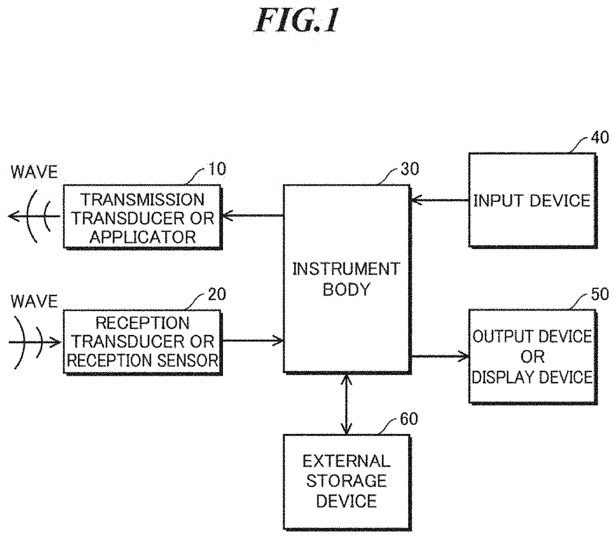
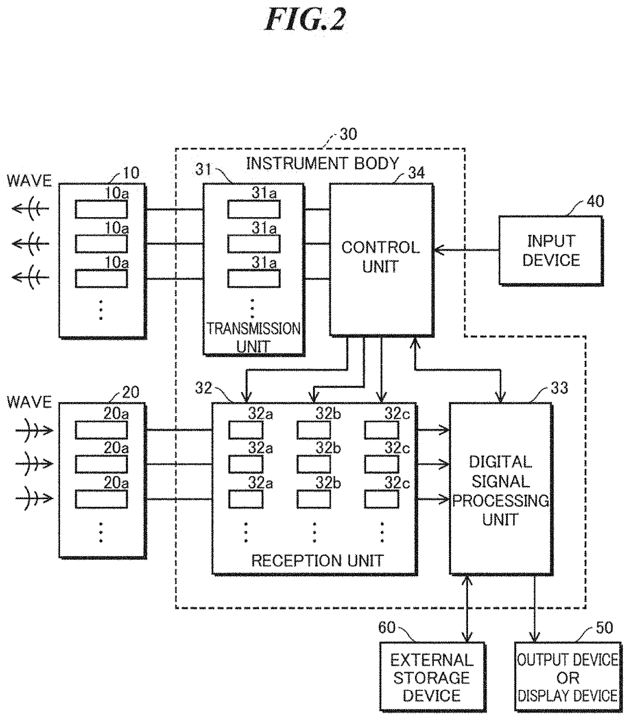
[0193]At first, the compositions of the measurement and imaging instrument according to the first embodiment of the present invention are explained. FIG. 1 shows a schematic representation (block map) of compositions of the measurement and imaging instrument according to the first embodiment of the present invention. As shown in FIG. 1, the measurement and imaging instrument is equipped with a transmission transducer (or an applicator) 10, a reception transducer (or a reception sensor) 20, an instrument body 30, an input device 40, an output device (or a display device) 50, and an external storage (memory) device 60. Here, the transmission transducer 10 and the reception transducer 20 can also be installed into one body or combined to realize a transmission and reception sensor.

[0194]FIG. 2 shows the specific schematic representation (block map) of compositions of a body of instrument shown in FIG. 1. Mainly, the body of instrument 30 is equipped with a transmissio...

« 2nd embodiment »

«2nd Embodiment»

[0801]Next, the compositions of the measurement and imaging instrument or the communication instrument according to the second embodiment of the present invention are explained. FIG. 1 shows a schematic representation (block map) of compositions for the active-type of instrument according to the first embodiment of the present invention; and FIG. 2 shows the specific schematic representation (block map) of compositions of a body of instrument shown in FIG. 1. In the second embodiment of the present invention, passive-type of instruments are used. Thus, at least the instruments according to the second embodiment are equipped with no transmission transducers and neither wire lines nor wireless lines for transferring drive signals from the control unit to the transmission transducers.

[0802]Regarding the active-type instrument according to the first embodiment, referring to FIGS. 1 and 2 showing a schematic representation (block map) of compositions of instrument, the co...

3rd embodiment

[0892]Being dependent on a frequency, a bandwidth, an intensity or a mode, etc., the waves such as electromagnetic waves, lights, mechanical vibrations, acoustic waves or thermal waves exhibit different behaviors. As far, many transducers for various type waves are developed and the waves themselves, the waves' transmission waves, reflection waves, refraction waves, diffraction waves or scattering waves are used for imaging. For instance, it is well known that on non-destructive examinations, medicines or sonars, ultrasounds, i.e., acoustic waves with higher frequencies, are used. Also on radars, electromagnetic waves with proper frequencies with respect to observation objects are used such as microwaves, terahertz waves, infrared rays, visible waves or radioactive rays such as an X-ray, etc. These are also for other waves.

[0893]On the imagings using such waves, amplitude data obtained via the quadrature detection, the envelope detection or the square detection are displayed in a gr...


PUM


Abstract

A measurement and imaging instrument capable of beamforming with high speed and high accuracy without approximate calculation. The instrument includes a reception unit which receives a wave arriving from a measurement object to generate a reception signal; and an instrument main body which performs a lateral modulation while superposing two waves in a two-dimensional case and three or four waves in a three-dimensional case in beamforming processing of the reception signal in which at least one wave arriving from the measurement object is processed as being transmitted or received in the axial direction or directions symmetric with respect to the axial direction to generate a multi-dimensional reception signal, performs Hilbert transform with respect to the multi-dimensional reception signal, and performs partial derivative processing or one-dimensional Fourier transform to generate analytic signals of the multi-dimensional reception signals of the two waves or the three or four waves.

Description

CROSS-REFERENCE TO RELATED APPLICATION[0001]The present application is a Continuation-In-Part of U.S. patent application Ser. No. 14 / 730,583 filed on Jun. 4, 2015 (inventors: Dr. Chikayoshi Sumi, an associate professor of Sophia University, Tokyo Japan and Mr. Naoto Yamazaki, a master student of Chikayoshi Sumi's laboratory). The disclosure of that application is incorporated herein by reference.[0002]Further, the present application claims priority from Japanese Patent Applications No. 2017-100947 filed on May 22, 2017, No. 2017-122554 filed on Jun. 22, 2017, No. 2017-137185 filed on Jul. 13, 2017, No. 2017-144588 filed on Jul. 26, 2017, No. 2017-157256 filed on Aug. 16, 2017, No. 2017-157590 filed on Aug. 17, 2017, No. 2017-207592 filed on Oct. 26, 2017, No. 2017-225982 filed on Nov. 24, 2017, No. 2017-242013 filed on Dec. 18, 2017, and No. 2017-245377 filed on Dec. 21, 2017 (inventor: Dr. Chikayoshi Sumi, an associate professor of Sophia University), the contents of which are inc...

Claims


Application Information

Patent Timeline
Patent Type & Authority Applications(United States)
IPC IPC(8): G01S7/52A61B6/00G01S15/89A61B8/00G01S17/90
CPCG01S7/52039A61B8/4488G01S15/89A61B8/00G01S7/52025G01S15/8915G01S7/52046G01S15/8997G01S17/90G01S7/52038G01S7/52047G01S7/52041G01S7/52023G01S7/52033G01S7/52019A61B6/00
Inventor SUMI, CHIKAYOSHIYAMAZAKI, NAOTO
Owner SUMI CHIKAYOSHI
Why Eureka
Try Eureka