
High-fidelity 3D printing using flashing photopolymerization

a photopolymerization and high-fidelity technology, applied in the field of micro-scale 3d printing methods, to achieve the effect of poor resolution

Pending Publication Date: 2021-12-30
RGT UNIV OF CALIFORNIA
View PDF3 Cites 3 Cited by
  • Summary
  • Abstract
  • Description
  • Claims
  • Application Information

AI Technical Summary

Benefits of technology

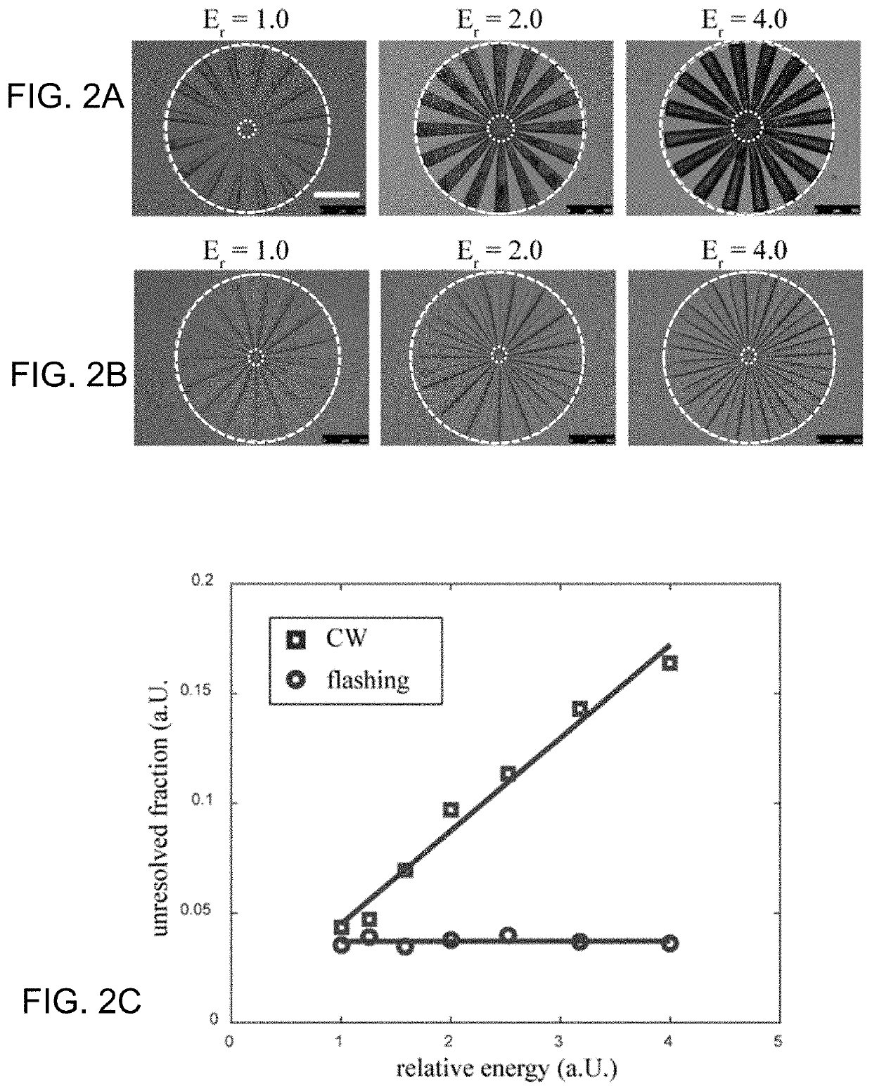
The present invention provides a method for improving the resolution of photopolymerization techniques used in 3D printing. This is achieved through the use of flashing photopolymerization (“FPP”), which minimizes scattering caused by light exposure. The method involves chronologically managing the order of three events: light exposure, polymerization, and opacification. By exposing the material only when there is minimal scattering, the exposure pattern is not perturbed by scattering, resulting in improved resolution. In one aspect of the invention, a 3D printing system uses flashing exposure for photopolymerization, with the resolution greatly improved compared to the use of a CW light source. The method can be implemented using a digital micro-mirror device and a pulsed light source. The printing volume can have a thickness within a range of from 1 and 500 microns. The platform can move either by incremental separation or continuous movement, and the flash duration can be adjusted to avoid light scattering. Overall, the invention provides a more precise and refined method for 3D printing.

Problems solved by technology

First, the flash exposure acts to generate a large number of free radicals.

Method used


Image

  • High-fidelity 3D printing using flashing photopolymerization
  • High-fidelity 3D printing using flashing photopolymerization
  • High-fidelity 3D printing using flashing photopolymerization

Examples


Embodiment Construction

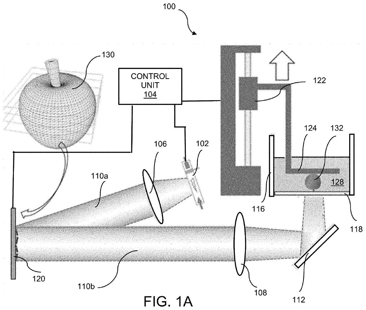
[0022]An embodiment of a printer for performing the inventive method for high fidelity 3D printing by flashing photopolymerization, i.e., “FPP 3D”, is shown in the schematic of FIG. 1A. The printer 100 uses a xenon flash tube 102 as the light source, which is connected to an electrical control unit 104. The light is projected along optical pathway 110a through optical lens 106 (or a lens assembly) to a digital micro-mirror device (DMD) 120 which modulates the light with the photomask image, represented by sample image 130, which, in the illustrated example, is an apple. Modulated light follows the optical path 110b through lens (or lens assembly) 108 for projection onto the transparent anti-adhesion substrate 118. As illustrated, optical path 110b is directed to substrate 118 by mirror 112. A motorized stage 122 is used to control the motion of the sample supporting platform 124. Control unit 104 controls and synchronizes activation of flash tube 102, manipulation of DMD 120 to proj...


PUM

PropertyMeasurementUnit
thicknessaaaaaaaaaa
thicknessaaaaaaaaaa
peak poweraaaaaaaaaa

Abstract

A method and system for microscale 3D printing achieve high-fidelity fabrication through the control of the light exposure time. A single pulse of light is used to initiate polymerization of a pre-polymer solution to minimize scattering-induced resolution deterioration. The printed object is fabricated in a layer-by-layer construction where each layer is formed through exposure to a single light pulse.

Description

RELATED APPLICATIONS[0001]This application claims the benefit of the priority of Provisional Application No. 63 / 044,824, filed Jun. 26, 2020, which is incorporated herein by reference in its entirety.GOVERNMENT RIGHTS[0002]This invention was made with government support under Grants No. EB021857 and HD090662 awarded by the National Institutes of Health and Grant No. CMMI1644967 awarded by the National Science Foundation. The government has certain rights in the invention.FIELD OF THE INVENTION[0003]The present invention relates to a micro-scale 3D printing method to achieve high-fidelity fabrication through the control of the light exposure time, and more particularly to use of a short pulse light source to minimize loss of resolution caused by scattering.BACKGROUND[0004]Photopolymerization-based 3D printing techniques are powerful tools in 3D freeform structure fabrication. They are able to fabricate micro- and nano-scale complex-geometry structures that are difficult to achieve us...

Claims


Application Information

Patent Timeline
Patent Type & Authority Applications(United States)
IPC IPC(8): B29C64/129B29C64/245B29C64/286B29C64/273B29C64/232B33Y10/00B33Y30/00
CPCB29C64/129B29C64/245B29C64/286B33Y30/00B29C64/232B33Y10/00B29C64/273
Inventor YOU, SHANGTINGCHEN, SHAOCHEN
Owner RGT UNIV OF CALIFORNIA
Learn More