Magnetic particle and method

a magnetic particle and particle technology, applied in the field of magnetic particle and method, can solve the problems of limited particle size, preventing the use of bioassays, and affecting the magnetic properties of particles, and achieves the effects of high magnetic anisotropy, high degree of control over the magnetic response, and extreme precision in the engineering of the magnetic properties of the mcs

Active Publication Date: 2022-01-13
CAMBRIDGE ENTERPRISE LTD
View PDF0 Cites 0 Cited by
  • Summary
  • Abstract
  • Description
  • Claims
  • Application Information

AI Technical Summary

Benefits of technology

[0060]In preferred forms, the MCs may be characterized by a magnetization direction parallel to the surface normal of the microdisc, as well as coercive magnetization reversal, and a high magnetic anisotropy. These properties may all enable a higher degree of control over their magnetic response and hence their mechanical behaviour in a fluid under the influence of an external magnetic field.
[0061]The physical vapour deposition process which is preferably used to fabricate the particles, or MCs, enables sub-nm control in the deposition of the magnetic thin films that form the MCs, and thus offers extreme precision in the engineering in the magnetic properties of the MCs. This may advantageously enable them to be tailored to different applications. Further, barcodes (or other readable information) may be lithographically added to the surface of MCs, and the surface materials may be chosen for optimal functionalization with molecules of interest.

Problems solved by technology

The size of these particles is limited by the fact that if the particles are made larger, beyond approximately 20 nm, the particles become ferromagnetic and the effect of the stray magnetic field of one particle on other particles disadvantageously leads to magnetic agglomeration of the particles, which prevents their use in bioassays.
This is undesirable because the purpose of using magnetic particles in biotechnology applications is to be able to steer, or direct the motion of, particles suspended in a liquid or fluid medium by applying an external magnetic field.
If the magnetic particles agglomerate, then this cannot be achieved.
However, in practice these systems suffer from limited multiplexing (limited number of different proteins that can be identified) due to limited ability to distinguish with certainty between the channels of the multiplex in assay results.

Method used


Image

  • Magnetic particle and method
  • Magnetic particle and method
  • Magnetic particle and method

Examples


Embodiment Construction

[0062]Specific embodiments of the invention will now be described by way of example, with reference to the accompanying drawings in which:

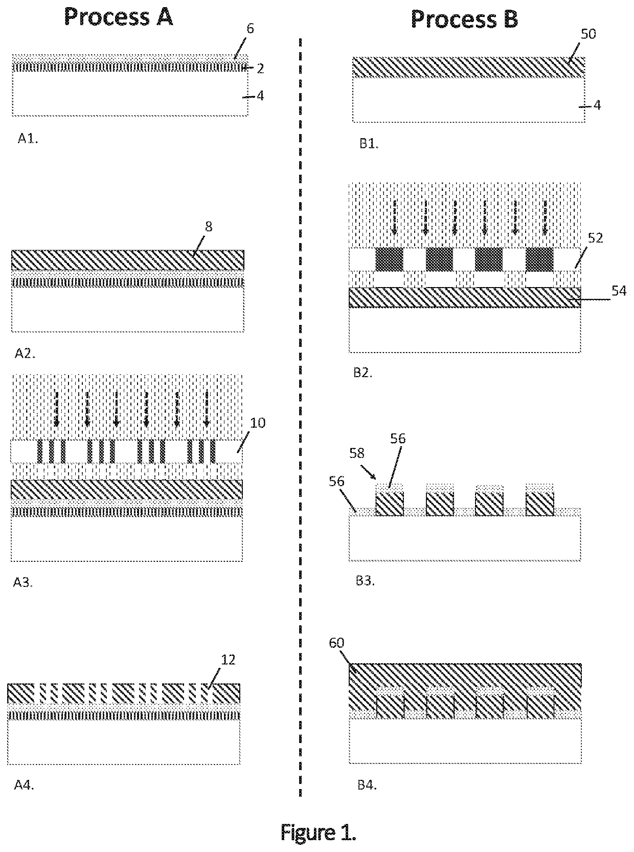
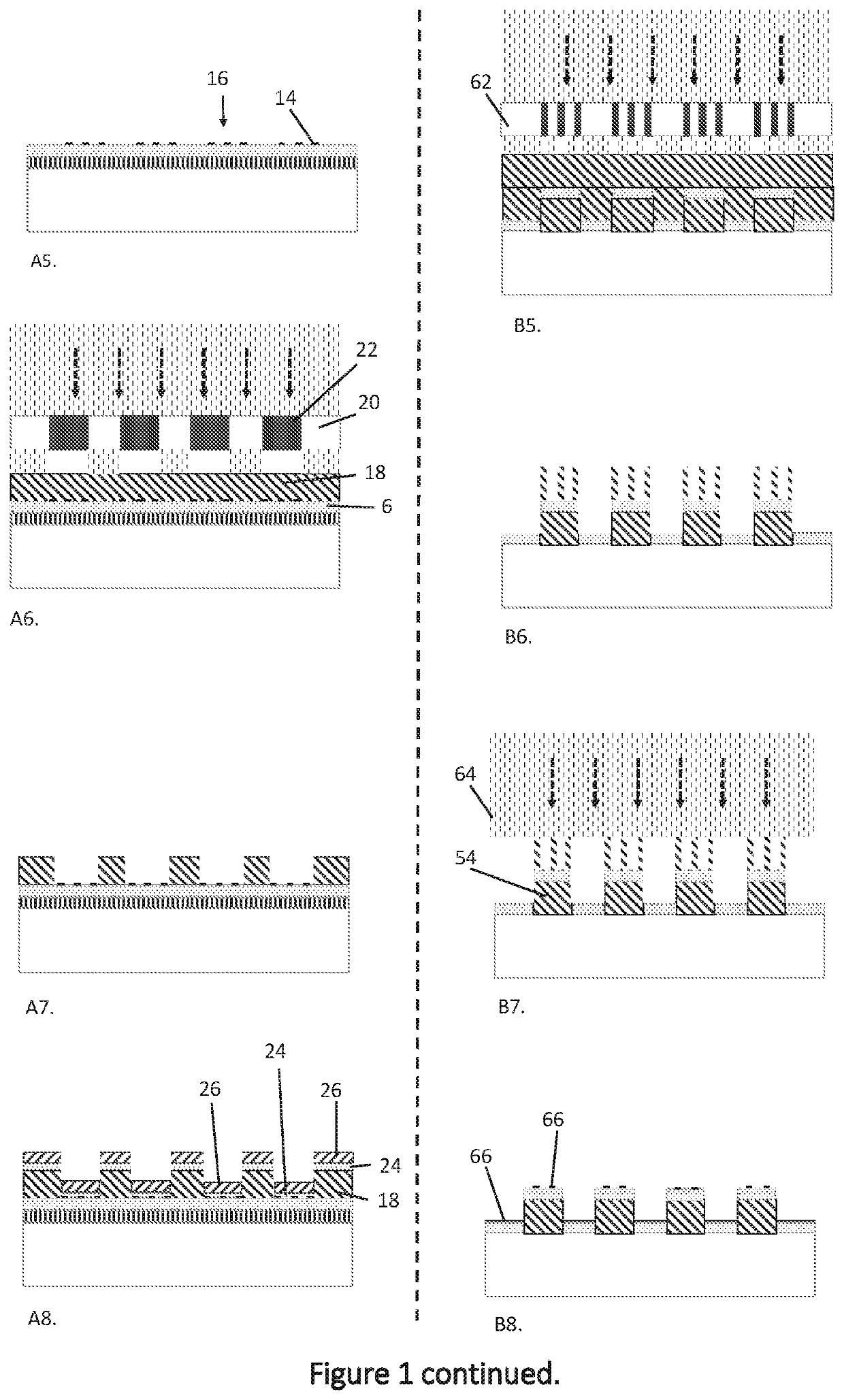
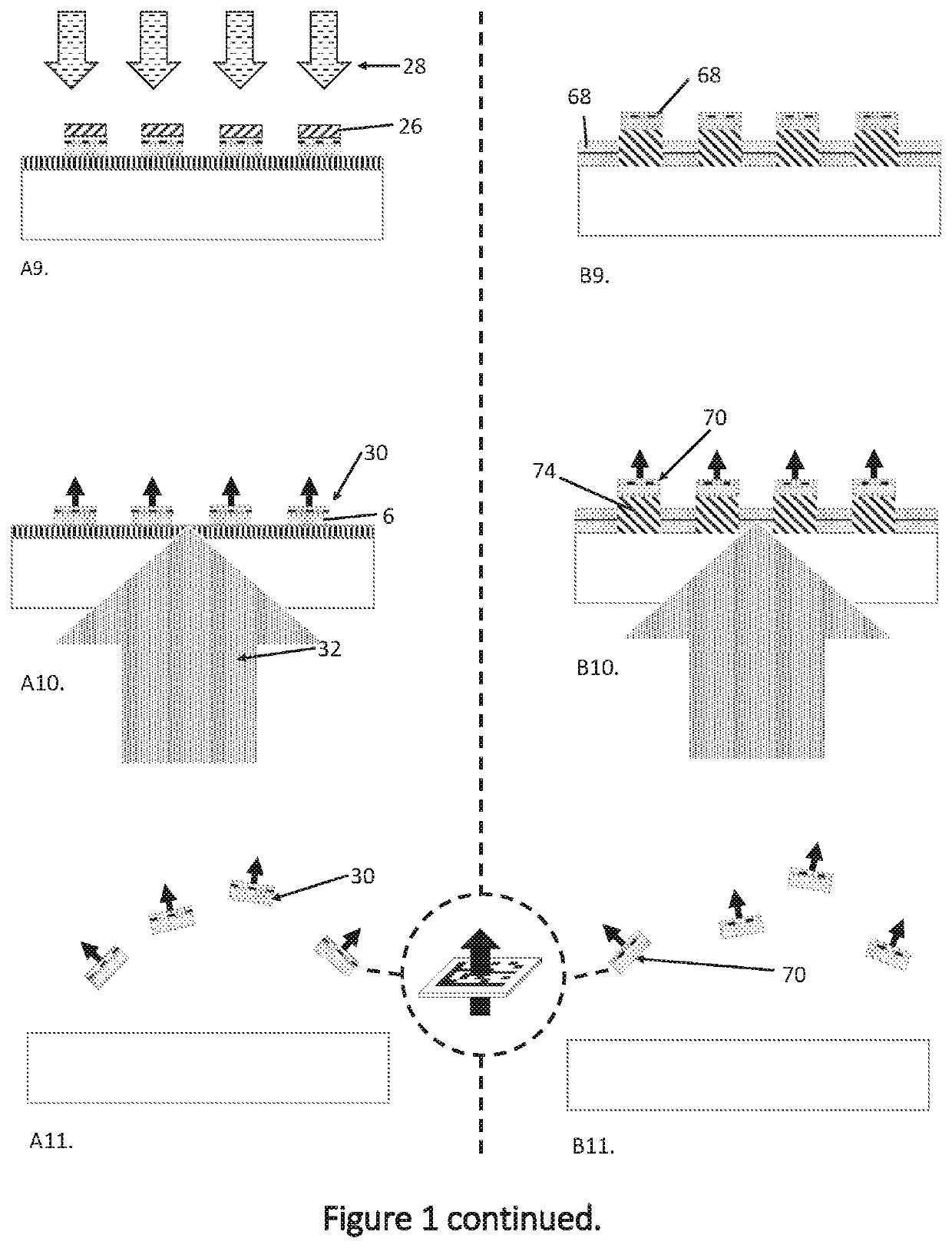
[0063]FIG. 1 illustrates steps in two processes, Process A and Process B, for the fabrication of magnetic particles according to first and second embodiments of the invention;

[0064]FIG. 2 is a polar magneto-optical Kerr effect (MOKE) measurement of the magnetic response of the magnetic thin film Au(100.0) / Ta(2) / Pt(4) / CoFeB(0.6) / Pt(1.2) / CoFeB(0.6) / Pt(1.2) / CoFeB(0.6) / Pt(1.2) / CoFeB(0.6) / Pt(5.0) used in the particles of the embodiments;

[0065]FIGS. 3(a) and 3(b) illustrate how the readable code and the magnetic states in particles according to the embodiments are linked to ensure that the readable code may always be aligned to an external detector, such as a camera or barcode reader, by an applied magnetic field, and show images of readable codes of particles imaged by a detector;

[0066]FIG. 4 illustrates stray field strength as a function of distance f...


PUM

PropertyMeasurementUnit
magnetisationaaaaaaaaaa
thicknessaaaaaaaaaa

Abstract

A magnetic particle (30, 70) has a layered structure (6, 56) between a top surface of the particle and an opposed bottom surface of the particle. Layers of the structure include one or more nonmagnetic layer(s) and one or more magnetized layer(s). The ratio of a lateral dimension of the one or more magnetized layers to the aggregate thickness of the magnetized layer or layers is greater than 500. A plurality of such magnetic particles (30, 70) can be functionalised and marked with readable codes (16, 66) corresponding to the functionalisation, for use for performing assays such as bioassays.

Description

[0001]The invention relates to a magnetic particle, and methods of making and using magnetic particles.BACKGROUND ART[0002]Techniques for using an applied magnetic field to exert mechanical forces on individual magnetic particles have been leveraged in various biotechnology applications.[0003]One important commercial use for magnetic nanoparticles and microparticles is currently for bioassays, to isolate and identify biological molecules. Superparamagnetic iron-oxide nanoparticles (SPIONs) are conventionally used for this commercial range of applications, because they offer the property of migrating towards an external magnetic field source. This enables particles to be steered by the application of an external magnetic field towards a desired location for reading the assay information. These particles are nanoparticles (5-20 nm in diameter) made by colloidal chemistry methods. The size of these particles is limited by the fact that if the particles are made larger, beyond approxima...

Claims


Application Information

Patent Timeline
Patent Type & Authority Applications(United States)
IPC IPC(8): H01F10/26G01N33/543
CPCH01F10/265G01N33/54326H01F41/34
Inventor VERHEYEN, JEROENVEMULKAR, TARUNCOWBURN, RUSSELL
Owner CAMBRIDGE ENTERPRISE LTD
Why Eureka
Try Eureka