
Display device and mobile terminal including same

a display device and mobile terminal technology, applied in static indicating devices, instruments, acquiring/reconfiguring fingerprints/palmprints, etc., can solve the problems of increasing manufacturing costs, lowering yield, and reducing yield, so as to reduce the driving voltage of the pixel. the effect of reducing the luminance of the display pixels and simplifying the structure of the display panel

Pending Publication Date: 2022-01-20
LG DISPLAY CO LTD
View PDF1 Cites 3 Cited by
  • Summary
  • Abstract
  • Description
  • Claims
  • Application Information

AI Technical Summary

Benefits of technology

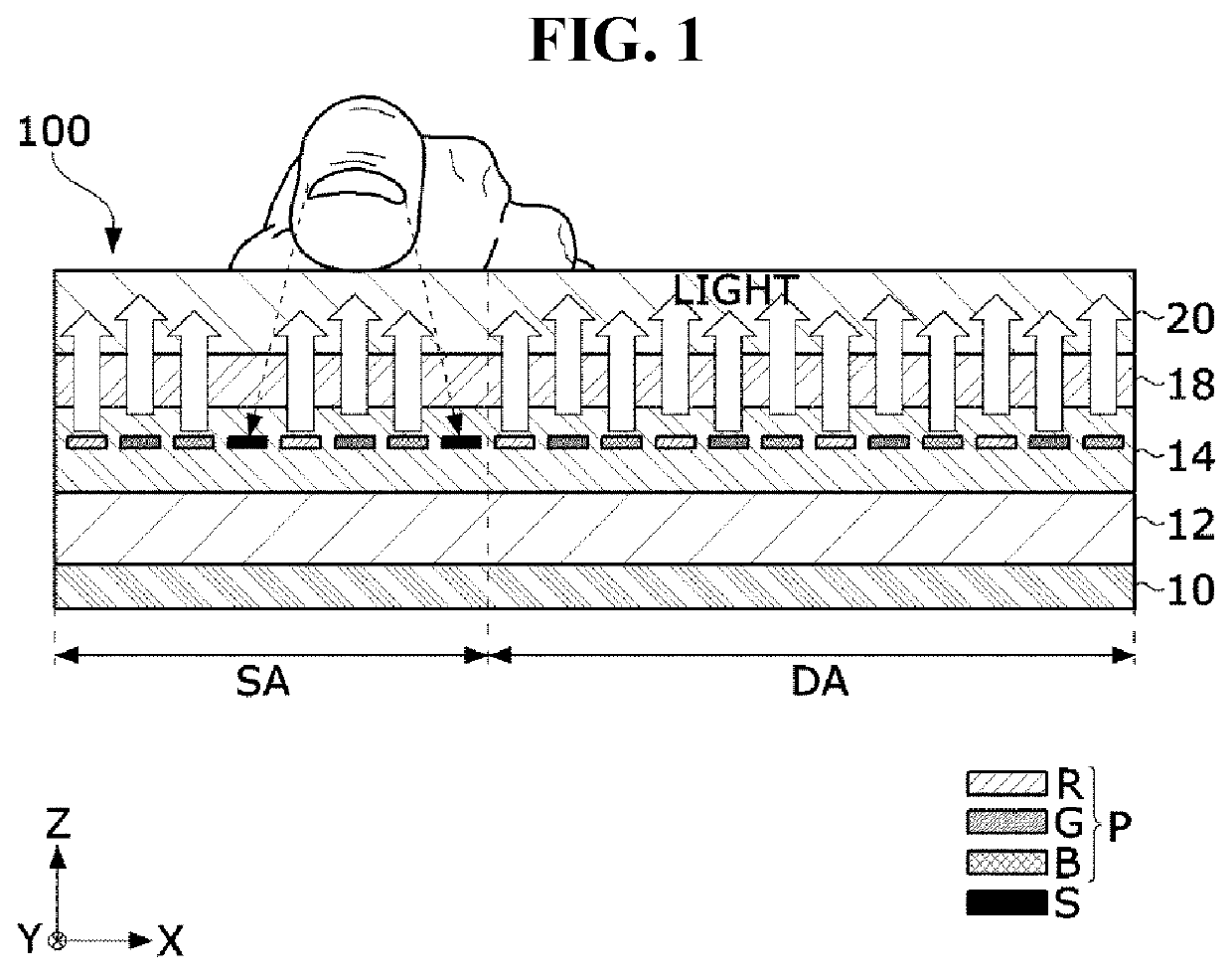
This patent aims to provide a display device and mobile terminal with a photosensor embedded in the display panel, allowing for a more secure and adjustable exposure time for the photosensor without affecting the luminance of the display pixels. By sharing power lines and signal lines in the pixel and photosensor driving circuits, the display panel can also include sensor pixels for sensing fingerprint. The exposure time of the sensor pixels can be adjusted by lowering the voltage applied to both the display pixels and the sensor pixels. The sensing accuracy and sensitivity can also be improved by extending the exposure time of the sensor pixels up to the active interval.

Problems solved by technology

Due to the fingerprint sensor, there have been many restrictions on the screen design of the smartphone.
For example, a conventional button-type fingerprint sensor was placed below the screen of a display device, and thus it was an obstacle which made it impossible to expand the screen size to implement a full-screen display.
In order to implement FOD, since a camera needs to be placed below the screen, the thickness of the display device increases, and the assembly process of a display panel and the camera is added, resulting in a problem of lowering yield and increasing manufacturing cost.

Method used


Image

  • Display device and mobile terminal including same
  • Display device and mobile terminal including same
  • Display device and mobile terminal including same

Examples


Embodiment Construction

[0038]The advantages and features of the present disclosure and methods for accomplishing the same will be more clearly understood from aspects described below with reference to the accompanying drawings. However, the present disclosure is not limited to the following aspects but may be implemented in various different forms. Rather, the present aspects will make the disclosure of the present disclosure complete and allow those skilled in the art to completely comprehend the scope of the present disclosure. The present disclosure is only defined within the scope of the accompanying claims.

[0039]The shapes, sizes, ratios, angles, numbers, and the like illustrated in the accompanying drawings for describing the aspects of the present disclosure are merely examples, and the present disclosure is not limited thereto. Like reference numerals generally denote like elements throughout the present specification. Further, in describing the present disclosure, detailed descriptions of known r...


PUM

PropertyMeasurementUnit
DAaaaaaaaaaa
area DAaaaaaaaaaa
area DAaaaaaaaaaa

Abstract

A display device and a mobile terminal including the same includes a display area in which a first group of display pixels to which pixel data is written are arranged, and a sensing area in which a second group of display pixels and a plurality of sensor pixels are arranged; each of the display pixels includes a pixel circuit configured to drive a light emitting element; each of the sensor pixels includes a photosensor driving circuit configured to drive a photodiode; a low potential power voltage and a pixel driving voltage are applied to the pixel circuit and the photosensor driving circuit; a cathode electrode of the light emitting element and the cathode electrode of the photodiode share the same metal electrode, and are commonly connected to a low potential power line to which the low potential power voltage is applied.

Description

CROSS-REFERENCE TO RELATED APPLICATION[0001]This application claims priority to and the benefit of Korean Patent Application No. 10-2020-0087901, filed Jul. 16, 2020, which is hereby incorporated by reference in its entirety.BACKGROUNDField of the Disclosure[0002]The present disclosure relates to a display device and a mobile terminal including the same.Description of the Background[0003]Electroluminescent display devices are roughly classified into inorganic light emitting display devices and organic light emitting display devices depending on the material of an emission layer. The organic light emitting display device of an active matrix type includes an organic light emitting diode (hereinafter, referred to as “OLED”) that emits light by itself, and has an advantage in that the response speed is fast and the luminous efficiency, luminance, and viewing angle are large. In the organic light emitting display device, the OLED is formed in each pixel. The organic light emitting displa...

Claims


Application Information

Patent Timeline
Patent Type & Authority Applications(United States)
IPC IPC(8): G06K9/00G09G3/3233H01L27/30H01L27/32
CPCG06K9/0004G09G3/3233G09G2360/14H01L27/323G09G2300/0421H01L27/307G09G3/3291G09G2320/0276H10K59/65G06V40/1318G09G2300/0819G09G2300/0842G09G2300/0861G09G2300/0426G09G3/3266G09G2310/0262G09G2310/08G09G2354/00H10K65/00G09G3/20H01L27/14678H10K39/32H10K59/40
Inventor HAN, MAN HYEOPCHOI, JOUNG MILEE, DONG GUN
Owner LG DISPLAY CO LTD
Learn More