Flow valve position sensor for an electrosurgical device

Pending Publication Date: 2022-02-03
GYRUS MEDICAL LTD
0 Cites 0 Cited by

AI-Extracted Technical Summary

Problems solved by technology

Currently, the flow valves in arthroscopic shavers are purely a mechanical interface, and do not provide any information with respect to the positioning of the flow valve with respect to the operation of the shaver.
Through normal operating procedures the motors produce latent heat and may require cooling.
If the motor is allowed to heat up excessively...

Method used

[0031]The sensing circuit may also be used to alert the user to open the flow valve 56 in the event that the motor 58 in the handpiece 3b ...

Benefits of technology

[0005]Embodiments of the present invention aim to provide a solution to the above identified drawbacks of the prior art by providing an improved handpiece for a surgical instrument having a sensing circuit to monitor the condition of the mechanical flow valve. This allows the condition of the valve to be electronic...

Abstract

A handpiece for a surgical instrument having a valve position sensing circuit arranged to detect the position of a valve arranged to control the flow of fluid through the suction lumen of the instrument. The distal end of the handpiece is arranged to couple to a cutting accessory. The handpiece comprises: a housing; a suction lumen within the housing extending from the distal end of the handpiece to a proximal end of the handpiece; a valve arranged to control the flow of fluid through the suction lumen; and a valve position sensing circuit arranged to detect a position of the valve. The valve position sensing circuit can be used to alert a surgeon if the valve is closed when it would be preferable for it to be open. For example, if the motor is overheating, the in-joint temperature is too high, or the RF component is activated.

Application Domain

Medical devicesInstrument handpieces +6

Technology Topic

Electric machinerySurgical instrument +8

Image

  • Flow valve position sensor for an electrosurgical device
  • Flow valve position sensor for an electrosurgical device
  • Flow valve position sensor for an electrosurgical device

Examples

  • Experimental program(1)

Example

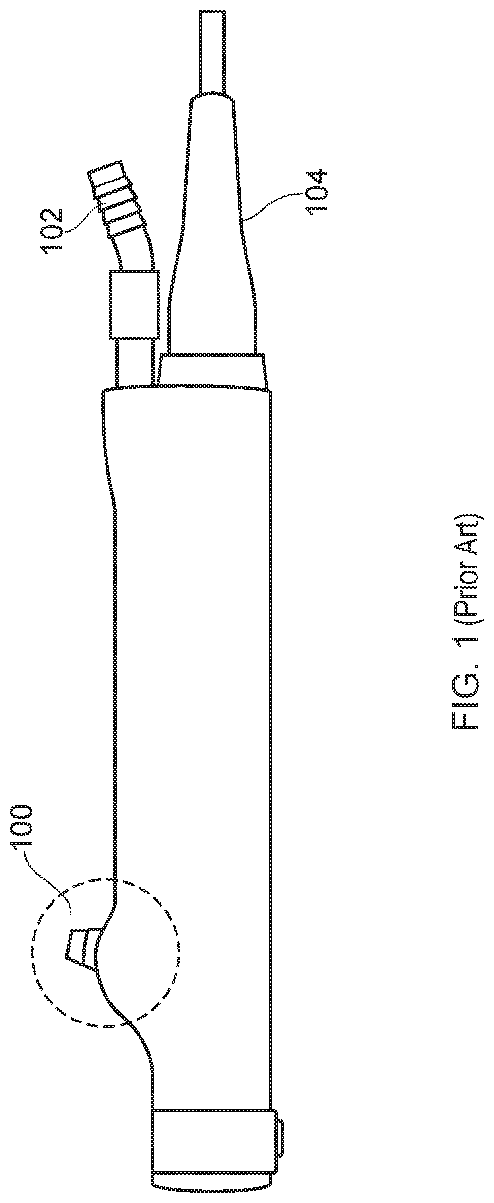
[0024]Referring to the drawings, FIG. 1 shows a prior art arrangement, the Stryker Formula Shaver Handpiece. The mechanical valve, operated by a lever 100, does not have any way of electronically monitoring the condition of the valve. A suction tube 102 is connected to the proximal end of the handpiece, as is a power cord 104.
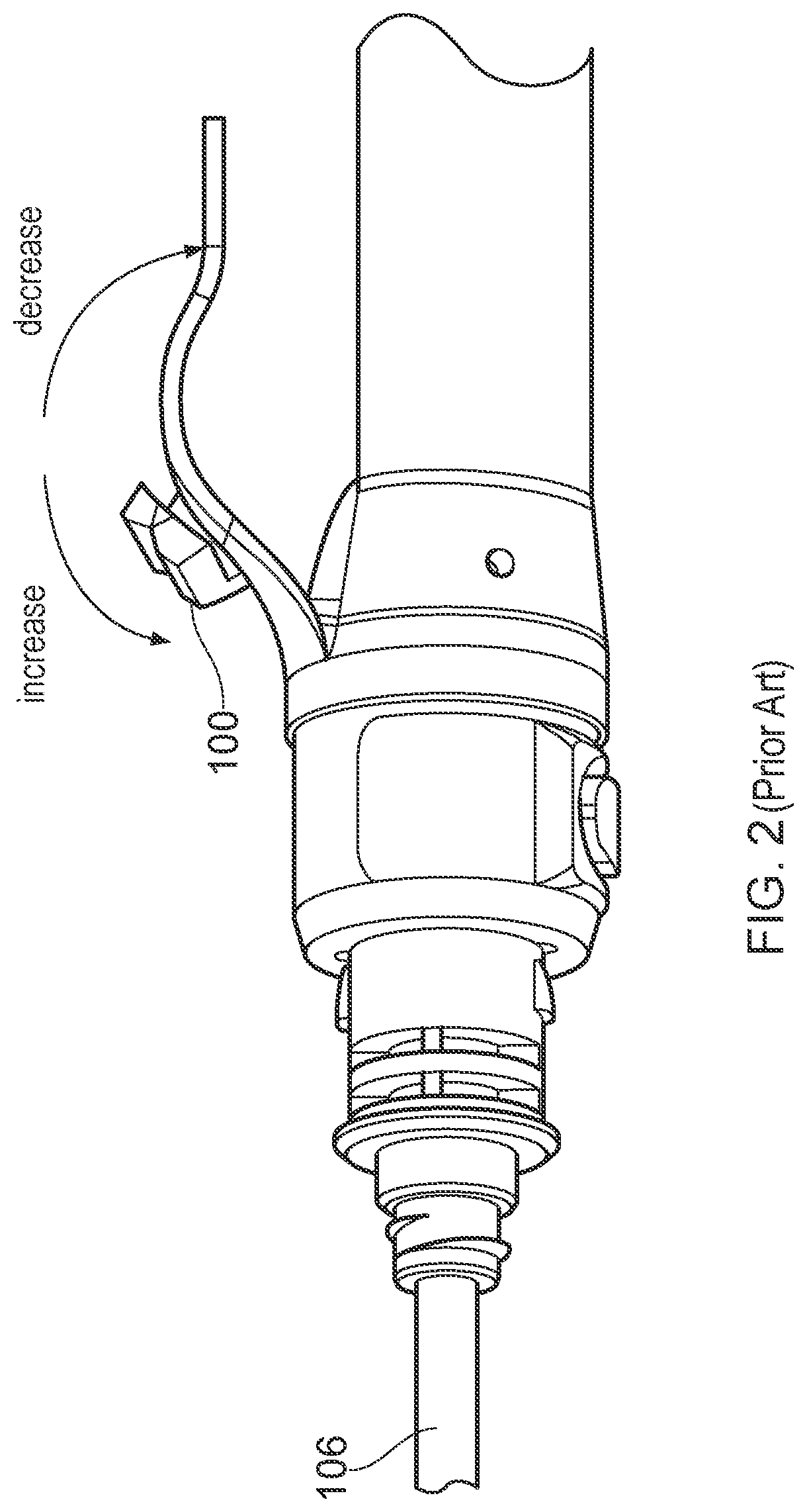
[0025]FIG. 2 shows the Stryker Formula Shaver in more detail. The mechanical valve is operated by moving the lever 100 between two positions. Increasing the flow of fluid through the valve is achieved by opening the valve, and decreasing the flow of fluid through the valve is achieved by closing the valve. At the distal end, the handpiece connects to a shaft 106, which would be connected to an end effector.
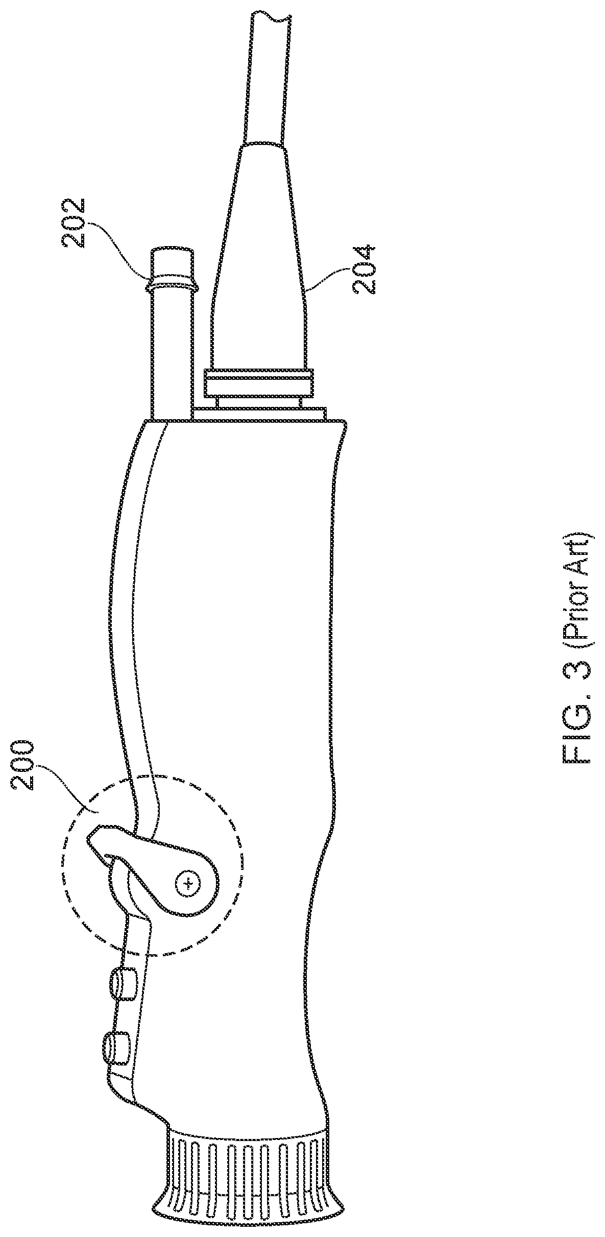
[0026]FIG. 3 shows a similar prior art arrangement, the Conmed Ergo Shaver Handpiece. Again, the mechanical valve is operated by a lever 200, and there is no way of electronically monitoring the condition of the valve. A suction tube 202 is connected to the proximal end of the handpiece, as is a power cord 204.
[0027]FIG. 4 shows electrosurgical apparatus including an electrosurgical generator 1 having an output socket 2 providing a radio frequency (RF) output, via a connection cord 4, for an electrosurgical instrument 3. The instrument 3 may have irrigation and suction tubes 14 which are connected to an irrigation fluid and suction source 10. Activation of the generator 1 may be performed from the instrument 3 via a handswitch (not shown) on the instrument 3, or by means of a footswitch unit 5 connected separately to the rear of the generator 1 by a footswitch connection cord 6. In the illustrated embodiment, the footswitch unit 5 has two footswitches 5a and 5b for selecting a coagulation mode or a cutting or vaporisation (ablation) mode of the generator 1 respectively. The generator front panel has push buttons 7a and 7b for respectively setting ablation (cutting) or coagulation power levels, which are indicated in a display 8. Push buttons 9 are provided as an alternative means for selection between the ablation (cutting) and coagulation modes.
[0028]The instrument 3 includes a handpiece 3a, a hollow shaft 3b extending in a distal direction away from the handpiece, and a distal end effector assembly 3c at the distal end of the shaft. A power connection cord 4 connects the instrument to the RF generator 1. The instrument may further be provided with activation buttons (not shown), to allow the surgeon operator to activate either the mechanical cutting function of the end effector, or the electrosurgical functions of the end effector, which typically comprise coagulation or ablation.
[0029]FIGS. 5 and 6 show the handpiece 3a in more detail. A suction lumen 50 extends through the handpiece 3a from the proximal end of the handpiece 52 to the distal end 54. At the proximal end of the handpiece 52, the suction lumen 50 connects to a further suction tube 14 (not shown in FIGS. 5 and 6) which is connected to the suction source 10 (not shown in FIGS. 5 and 6). At the distal end of the handpiece 54, the suction lumen 50 extends through the shaft 3b (not shown in FIGS. 5 and 6) to the end effector 3c (not shown in FIGS. 5 and 6). In a surgical procedure, irrigation fluid is introduced into the surgical site in order to serve as a transport medium for removing debris from the site. The irrigation fluid containing the debris is then sucked up through the suction lumen 50. The suction force is provided by the suction source 10. A valve 56 is provided to control the flow of fluid through the suction lumen 50. FIGS. 5 and 6 show a motor 58 which is connected to the generator 1 by the power cord 4 (not shown in FIGS. 5 and 6) attached to the proximal end of the handpiece 52. The motor 58 is used to provide power to a mechanical component in the end effector, for example, a mechanical shaver component. The motor 58 may be a DC electric motor. The motor 58 is operably connected to a clutch-type arrangement 59 which allows the motor 58 to actuate the mechanical component. The clutch-type arrangement 59 allows the mechanical component to engage and disengage from the motor 58.
[0030]FIGS. 5 and 6 illustrate one method of achieving the sensing circuit of the present invention, to have a magnet 60 connected to the flow valve lever 62 and a Hall Effect sensor 64 mounted in a static position on a circuit board 66 in the handpiece 3a. The circuit board 66 acts as a processor for the sensing circuit. The magnet 60 may be any magnetic element, for example, a permanent magnet. FIG. 5 illustrates the system when the flow valve 56 is in the open position. FIG. 6 illustrates the system when the flow valve 56 is in the closed position. The Hall Effect sensor 64 can detect any relative movement of the magnet 60 by detecting changes in a magnetic field surrounding the Hall Effect sensor 64, and consequently movement of the flow valve lever 62. This enables the position of the flow valve lever 62, and consequently the position of the flow valve 56 (i.e. whether the flow valve 56 is open or closed, or somewhere in between), to be monitored. In FIG. 5, the magnet 60 (and the lever 62) is in a first position and the valve 56 is consequently open. In FIG. 6, the magnet 60 (and the lever 62) has moved to a second position, and the valve 56 is consequently closed. The movement of the magnet 60 between these two positions is detectable by the Hall Effect sensor 64, which detects the relative movement of the magnet 60 via the change in magnetic field around the Hall Effect sensor 64. The Hall Effect sensor 64 sends a signal to the processor 66 to communicate the change in position. Based on this signal, the processor 66 can determine whether the valve 56 is open or closed. The condition of the valve 56 can then be communicated to a user of the instrument via a further signal on the handpiece 3a, or via the generator 1. For example, in the context of a RF shaver instrument, if the user is using the RF part of the instrument with the flow valve 56 closed, the handpiece 3b may provide tactile feedback to warn the user. Alternatively or additionally, the generator display 8 may display a warning to the user. This is desirable as it is known that the RF performance is enhanced when the flow valve 56 is open.
[0031]The sensing circuit may also be used to alert the user to open the flow valve 56 in the event that the motor 58 in the handpiece 3b is overheating and the flow valve 56 is closed. The flow of saline through the instrument can help to remove latent heat from the motor 58.
[0032]The sensing circuit may be used in conjunction with an in-joint temperature sensor to ensure that the saline temperature in the joint is not allowed to exceed a certain point. If the in-joint temperature is approaching unacceptable levels and the saline in the joint is not being exhausted because the flow valve 56 is closed, the user could be prompted to open the flow valve 56. The hot saline would then be removed from the surgical site, allowing cooling of the joint.
[0033]In various embodiments, any number of magnetic sensing elements 60 may be used to monitor the condition of the flow valve 56. Technologies used for magnetic field sensing include search coil, fluxgate, optically pumped, nuclear precession, SQUID, Hall-effect, anisotropic magnetoresistance, giant magnetoresistance, magnetic tunnel junctions, giant magnetoimpedance, magnetostrictive/piezoelectric composites, magnetodiode, magnetotransistor, fiber optic, magnetooptic, and microelectromechanical systems-based magnetic sensors, among others.
[0034]An example of an alternative to the magnet 60 and Hall Effect sensor 64 sensing circuit would be to use an accelerometer to monitor the movement of the flow valve lever.
[0035]The concepts of the present invention can be used on a wider suite of arthroscopic instruments as further embodiments, and they are not limited specifically to shaver instruments. In further embodiments the magnet may be included in the movable part of the flow control of many arthroscopic instruments.
[0036]Various modifications whether by way of addition, deletion, or substitution of features may be made to above described embodiment to provide further embodiments, any and all of which are intended to be encompassed by the appended claims.

PUM

no PUM

Description & Claims & Application Information

We can also present the details of the Description, Claims and Application information to help users get a comprehensive understanding of the technical details of the patent, such as background art, summary of invention, brief description of drawings, description of embodiments, and other original content. On the other hand, users can also determine the specific scope of protection of the technology through the list of claims; as well as understand the changes in the life cycle of the technology with the presentation of the patent timeline. Login to view more.

Similar technology patents

Node and a Method for use in a Wireless Communications System

ActiveUS20100279602A1improve performance
Owner:TELEFON AB LM ERICSSON (PUBL)

Managing vehicle efficiency

ActiveUS8155868B1improve performance
Owner:TOYOTA INFOTECHNOLOGY CENT CO LTD

Master-slave flip-flop and clocking scheme

ActiveUS7408393B1improve performancereduce propagation delay
Owner:MARVELL ASIA PTE LTD

Metadata storage system for cluster file system and metadata management method

ActiveCN102364474Aimprove performance
Owner:INST OF COMPUTING TECH CHINESE ACAD OF SCI +1

Classification and recommendation of technical efficacy words

  • improve performance

complex process management

InactiveUS20110208565A1improve performance
Owner:ECOMMERA

Feedback loop for spam prevention

InactiveUS7219148B2facilitate trainingimprove performance
Owner:MICROSOFT TECH LICENSING LLC
Why Eureka
Try Eureka