
Catheter Comprising a Flexible Flat Cable and FPCB and Method for Producing It

a flexible flat cable and catheter technology, applied in the direction of catheters, printed circuit aspects, sensors, etc., can solve the problems of preventing process automation and design extension, cumbersome design and manufacturing of high-density catheters, and limiting catheters to specific applications. , to achieve the effect of reducing the amount of material, ensuring the stability of the catheter, and ensuring the free space of the fpcb

Pending Publication Date: 2022-02-17
BERNER FACHHOCHSCHULE FUR TECHN & INFORMATIK
View PDF0 Cites 0 Cited by
  • Summary
  • Abstract
  • Description
  • Claims
  • Application Information

AI Technical Summary

Benefits of technology

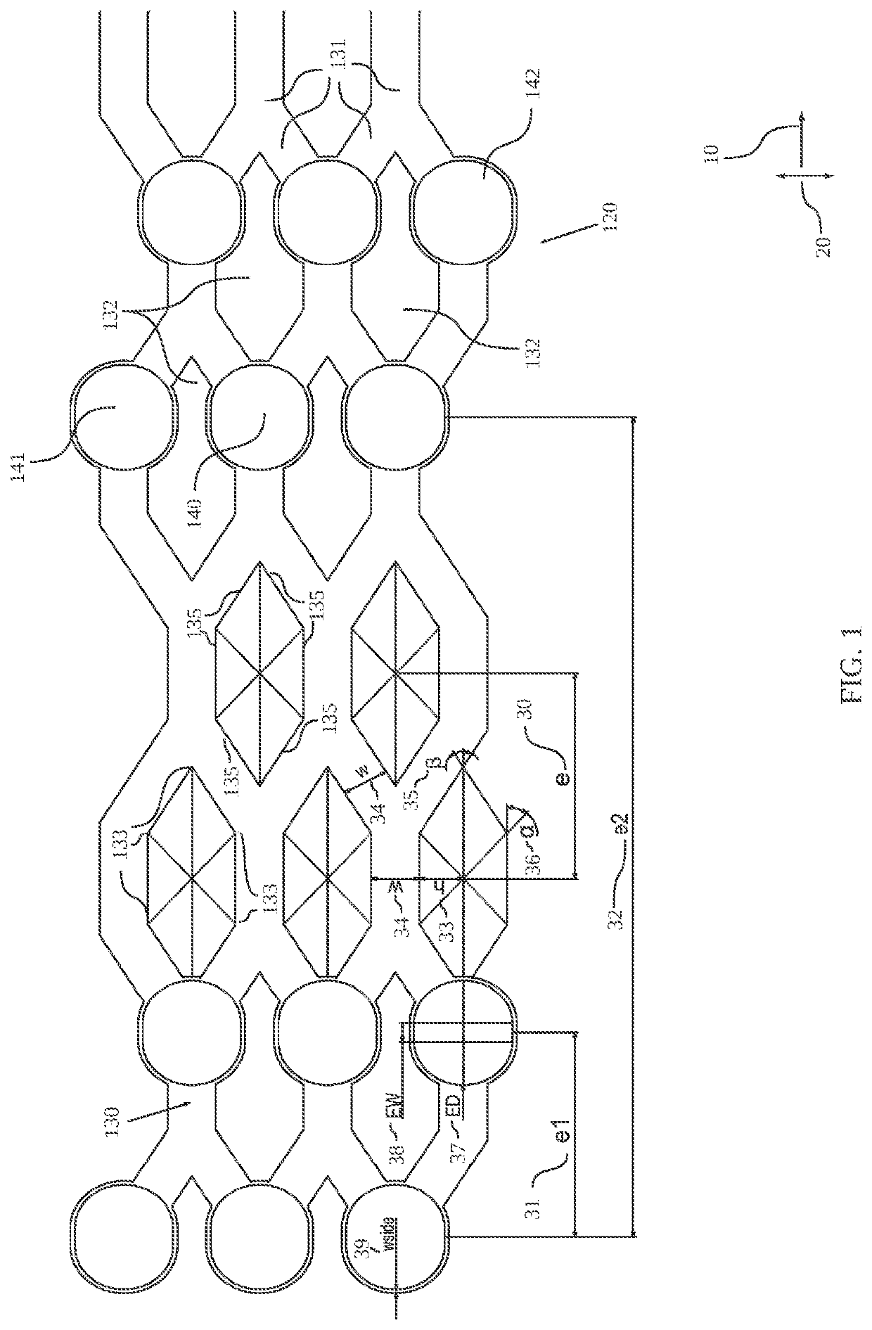
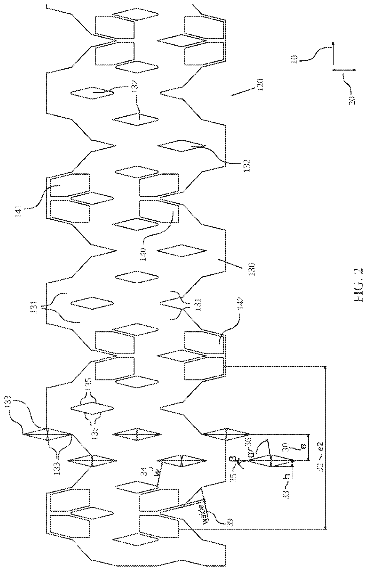
The present invention provides an improved concept and method to produce a medical device, particularly a catheter, with passive and / or active transducers that provide desired bendability, pushability, torquability, and kinking compensation or prevention. The catheter comprises a tube and a flexible printed circuit board (FPCB) that partially covers the catheter circumference on predetermined segments along the longitudinal axis of the catheter. The FPCB has sufficient free spaces to ensure the desired bendability and stability of the catheter. The FPCB can have a hexagonal or diamond basic pattern and can have any quantity or orientation to improve bending in different directions. The FPCB can also have electronic components placed on it, which can be seamlessly integrated into the catheter without interfering with its outside.

Problems solved by technology

However, design and manufacturing of high-density catheters is cumbersome due to typical soft material properties and small dimensions, respectively.
The resulting manual manufacturing is labour intensive and prevents process automation and design extensions.
Such catheters are limited to specific applications where no bendability and flexibility is required.
Furthermore, the presence of adhesives is undesirable in a cleanroom setting during manufacturing.

Method used


Image

  • Catheter Comprising a Flexible Flat Cable and FPCB and Method for Producing It
  • Catheter Comprising a Flexible Flat Cable and FPCB and Method for Producing It
  • Catheter Comprising a Flexible Flat Cable and FPCB and Method for Producing It

Examples


first embodiment

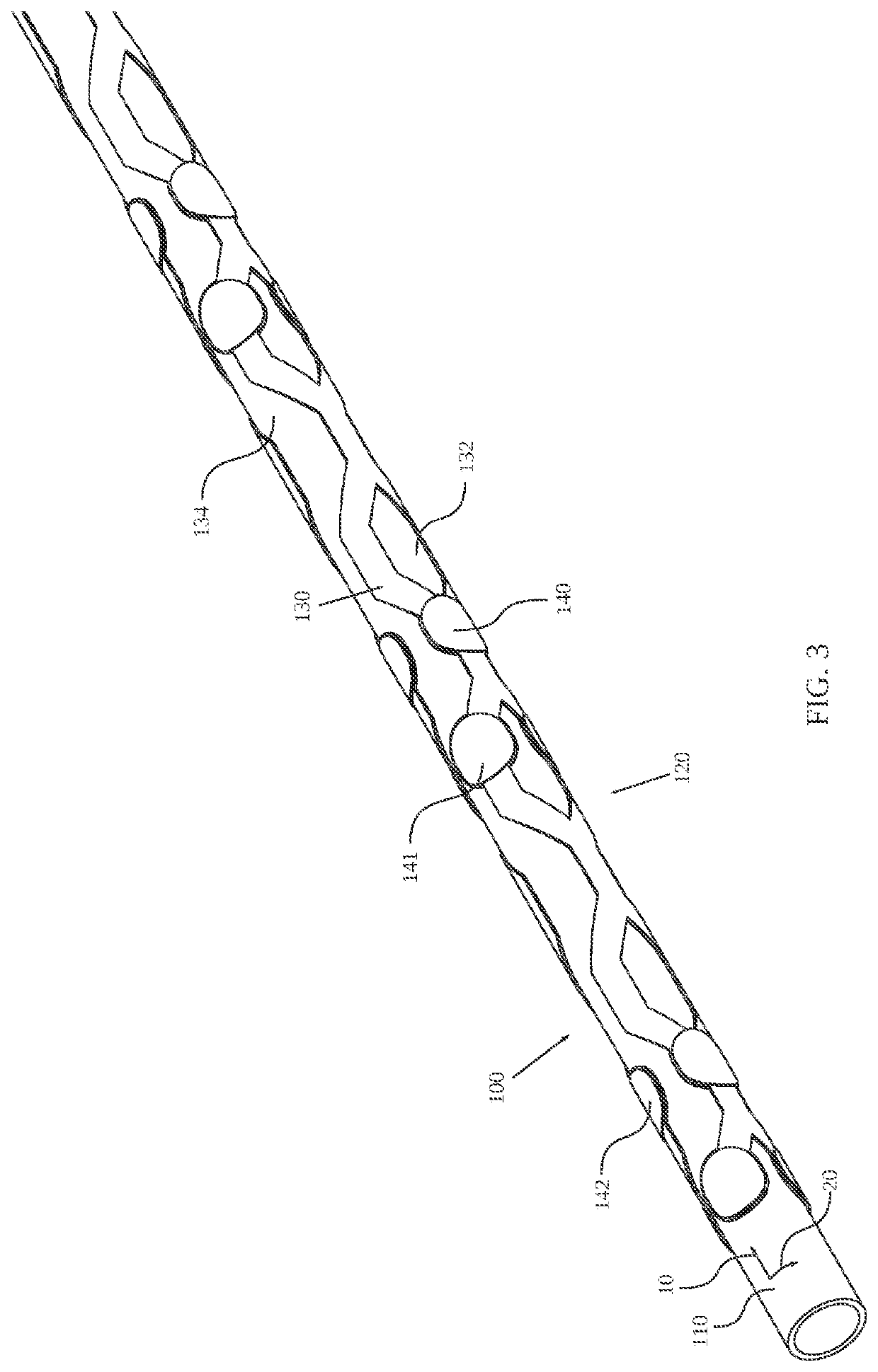
[0051]FIG. 3 shows a perspective view of a catheter 100 with a flexible printed circuit board, i.e. FPCB 120 according to the invention and FIG. 4 shows the catheter tube 110 of FIG. 3 with the FPCB 120 separated from the tube 110. The catheter 100 comprises at least the catheter tube 110 based on a polymer, preferably a thermoplastic polymer onto which the FPCB 120 was thermobonded on its circumference.

[0052]FIG. 4 shows that the FPCB 120 can be provided initially as a separate flat sheet and comprises a scaffold structure 130 and a plurality of transducer patches 140. The scaffold structure 130 comprises straight scaffolds 131 forming a periodic structure of FPCB free spaces 132. Transducer patches 140 are attached or integrated intermittently on every second corner of the hexagons, i.e. for every hexagon three corners where the straight scaffolds 131 are connected comprise such a round transducer patch 140. The diameter of the transducer patches 140 is larger than the width of th...

second embodiment

[0059]FIG. 5 shows a perspective view of a catheter 200 with a FPCB 120 according to the invention and FIG. 6 shows the catheter tube 110 of FIG. 5 with the FPCB 120 separated from the tube 110. The catheter 200 comprises at least the catheter tube 110 based on a polymer, preferably a thermoplastic polymer onto which is affixed the FPCB 120.

[0060]The FPCB 120 can be provided initially as a separate flat sheet as shown in FIG. 6 and comprises a scaffold structure 130 and a plurality of transducer patches 140. The scaffold structure 130 comprises a straight scaffold 131 forming a periodic structure of hollow openings with an interior hollow space 132.

[0061]Pairs of hexagonal transducer patches 140 are attached or integrated intermittently on a predetermined number of straight scaffolds 131 pairs but also can be of circular design. The diameter of the transducer patches 140 is not larger than the width of the straight scaffold 131.

third embodiment

[0062]FIG. 7 shows a perspective view of a catheter 300 with a FPCB 120 according to the invention and FIG. 8 shows the catheter tube 110 of FIG. 7 with the FPCB 120 separated from the tube 110. The catheter 300 comprises at least the catheter tube 110 based on a polymer, preferably a thermoplastic polymer onto which is affixed the FPCB 120. The FPCB 120 can be provided initially as a separate flat sheet as shown in FIG. 8 and comprises a scaffold structure 130 and a plurality of transducer patches 140. The scaffold structure 130 comprises straight scaffolds 131 forming a periodic structure of hollow hexagons with an interior hollow space 132. Transducer patches 140 are attached or integrated intermittently on every second corner of the hexagons, i.e. for every hexagon three corners where the straight scaffolds 131 are connected comprise such a round transducer patch 140. The diameter of the transducer patches 140 is larger than the width of the straight scaffolds 131 and therefore ...


PUM

PropertyMeasurementUnit
angleaaaaaaaaaa
angleaaaaaaaaaa
bending angleaaaaaaaaaa

Abstract

A catheter includes a catheter tube and a Flexible Printed Circuit Board, FPCB, wherein the FPCB covers essentially the catheter circumference for predetermined FPCB transducer segment length, especially at the distal portion, wherein the FPCB in the FPCB transducer segment includes a scaffold structure with a plurality of FPCB free spaces and one FPCB free surface portion creating maximum mechanical stability with the least amount of material and a FPCB scaffold structure which ensures maximum flexibility. The FPCB includes transducer patches which are connected by traces on the straight scaffolds of the scaffold structure. The FPCB free spaces are configured for preventing, circumventing and / or compensating the kinking behavious of the catheter tube.

Description

CROSS-REFERENCE TO RELATED APPLICATION[0001]This application claims priority to European Patent Application No. 20 190 962.9 filed Aug. 13, 2020, the disclosure of which is hereby incorporated by reference in its entirety.BACKGROUND OF THE INVENTIONField of the Invention[0002]The present invention relates to a catheter comprising a flexible flat cable and FPCB and a method producing it.Description of Related Art[0003]The increasing prevalence of patients with cardiovascular diseases and neurological disorders with the simultaneous medical progress has enforced the number as well as complexity of minimally invasive procedures over the past decades as shown by Benjamin Emelia J. et al., “Heart Disease and Stroke Statistics-2018 Update: A Report From the American Heart Association,” Circulation, vol. 137, no. 12, pp. e67-e492, March 2018. Advanced diagnostic and therapeutic catheters have been developed for such interventions. The trend goes towards catheters that integrate multiple tr...

Claims


Application Information

Patent Timeline
Patent Type & Authority Applications(United States)
IPC IPC(8): A61M25/00H05K1/02
CPCA61M25/0054H05K2201/10151A61M2025/0059H05K1/028A61B5/6852A61B18/1492A61B2018/0016A61N1/05H05K1/189H05K1/0283A61N1/0551A61N1/056A61B2562/166H05K2201/09063H05K2201/056H05K2201/0141
Inventor NIEDERHAUSER, THOMASKUERT, GERHARDJACOMET, MARCELWILDHABER, RETO ANDREAS
Owner BERNER FACHHOCHSCHULE FUR TECHN & INFORMATIK
Learn More