Thermal Insulation

a technology of thermal insulation and thermal insulation layer, which is applied in the field of thermal insulation, can solve the problems of high use temperature limit of these materials, insufficient thermal insulation of these materials, and surprisingly high bio-solubility level, so as to reduce not significantly affecting the high temperature performance of the fibre, and minimise the size of the surface crystallite phase

Active Publication Date: 2022-04-28
THERMAL CERAMICS UK
View PDF0 Cites 0 Cited by
  • Summary
  • Abstract
  • Description
  • Claims
  • Application Information

AI Technical Summary

Benefits of technology

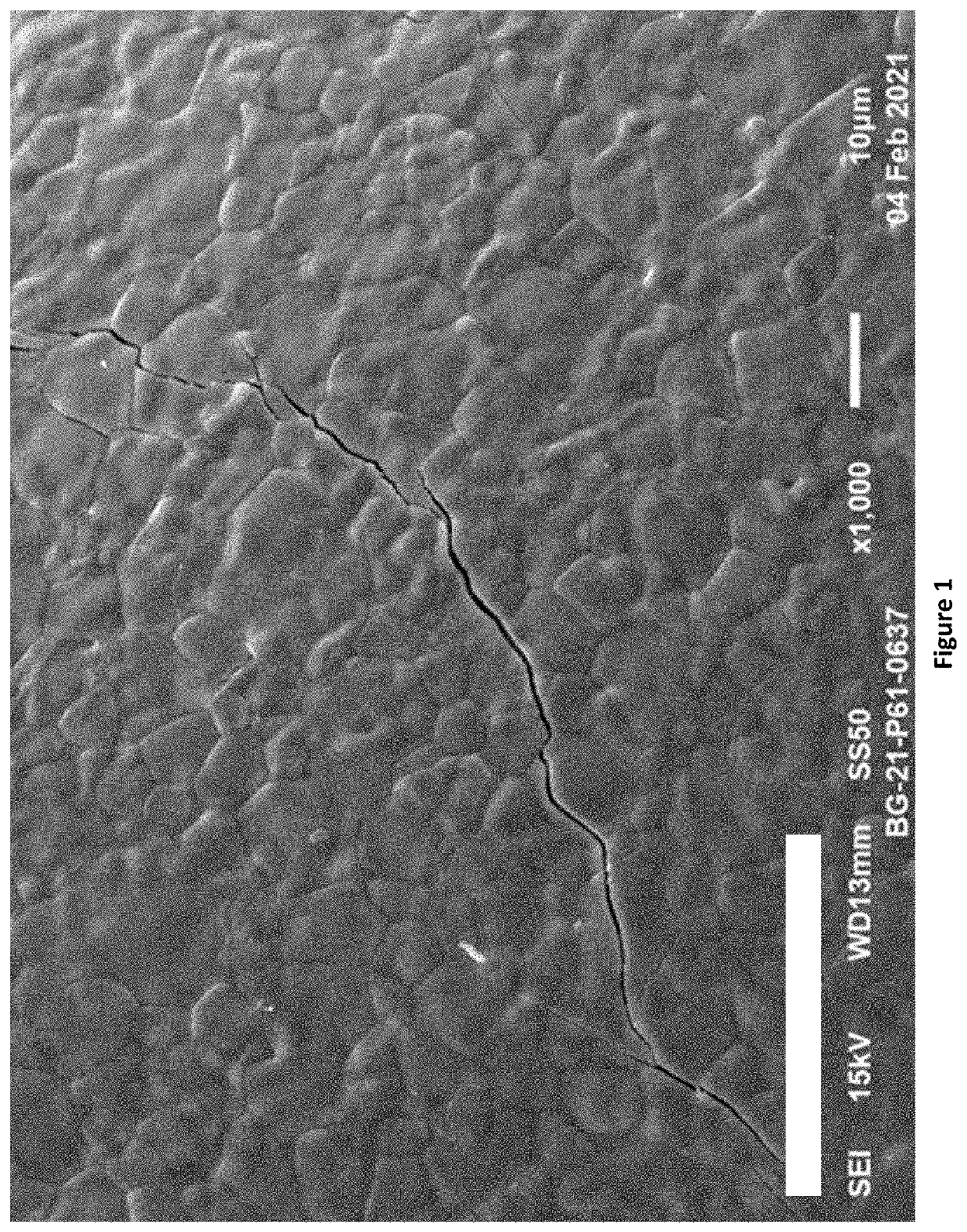
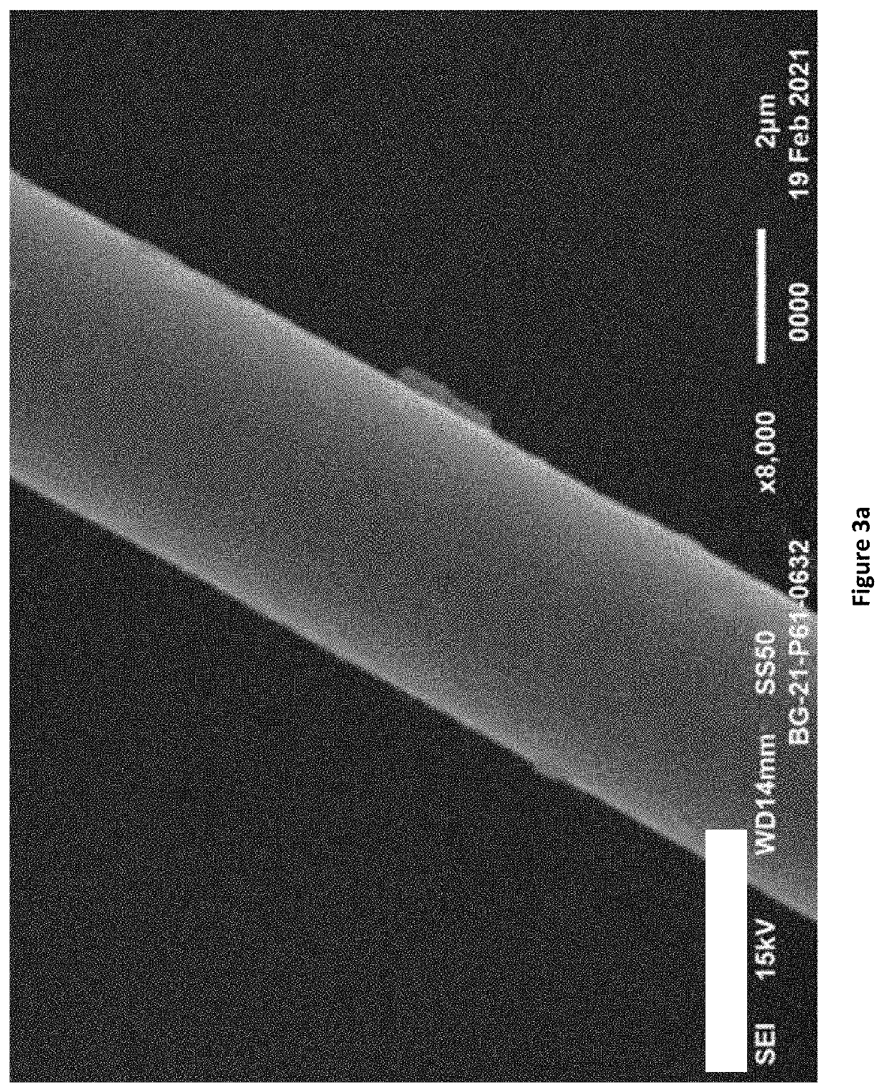
[0035]It has been found that there is a narrow compositional window in which a small amount of MgO unexpectedly inhibits the formation of large surface crystallite grains at high temperatures, whilst not significantly affecting the high temperature performance of the fibres. Large surface crystallite grains on fibres may result in the creation of stress points which adversely affects the mechanical properties of the fibres at high temperatures. Therefore, it is desirable to minimise the size of the surface crystallite phases formed at high temperatures when the fibres are in use.
[0127]Preferably the sum of magnesia and incidental impurities is greater or equal to 0.3 wt % or greater or equal to 0.4 wt %. The amount of magnesia and incidental impurities being sufficient to reduce the melt viscosity of the composition and enable fibres to be formed as described in previous aspects of the disclosure.

Problems solved by technology

While candidate silicate materials have been proposed, the use temperature limit of these materials have not been high enough to accommodate many of the applications to which high temperature resistant fibres are applied.
For example, such bio-soluble fibres exhibit high shrinkage at use temperatures and / or reduced mechanical strength when exposed to use temperatures ranging from 1000° C. to 1500° C. as compared to the performance of refractory ceramic fibres.
It was observed that lower Al2O3 levels resulted in a surprisingly high bio-solubility level.

Method used


Image

  • Thermal Insulation
  • Thermal Insulation
  • Thermal Insulation

Examples


Embodiment Construction

[0143]Fibres according to the disclosure and comparative fibres described herein have been produced at either the French production facilities in Saint Marcellin, France by spinning [made from the melt by forming a molten stream and converting the stream into fibre by permitting the stream to contact one or more spinning wheels]; or at the applicant's research facilities in Bromborough, England by spinning or alternatively by blowing [fibres made from the melt by forming a molten stream and converting the stream into fibre by using an air blast directed at the stream]. The disclosure is not limited to any particular method of forming the fibres from a melt, and other methods [e.g. rotary or centrifugal formation of fibres; drawing; air jet attenuation] may be used. The resultant fibres were then fed onto a conveyor belt and entangled by needling methods, as known in the art.

[0144]The raw materials used to produce the inorganic fibres of a preferred embodiment of the present disclosu...


PUM


Abstract

A process for the manufacture of inorganic fibres comprises: (a) selecting a composition and proportion of: (i) silica sand; (ii) lime comprising at least 0.10 wt % magnesia; and (iii) optional additives comprising a source of oxides or non-oxides of one or more of the lanthanides series of elements, or combinations thereof; (b) mixing the silica sand; lime; and optional additives to form a mixture; (c) melting the mixture in a furnace; and (d) shaping the molten mixture into inorganic fibres. The raw materials selection comprises composition selection and proportion selection of the raw materials to obtain an inorganic fibre composition comprising a range of from 61.0 wt % and 70.8 wt % silica; less than 2.0 wt % magnesia; less than 2.0% incidental impurities; and no more than 2.0 wt % of metal oxides and / or metal non-oxides derived from said optional additives; with calcia providing the balance up to 100 wt %; and wherein the inorganic fibre composition comprises no more than 0.80 wt % Al203 derived from the incidental impurities and / or the optional additives.

Description

CROSS-REFERENCE TO RELATED APPLICATIONS[0001]This application claims priority to United Kingdom Application No. 2016878.7, filed Oct. 23, 2020, United Kingdom Application No. 2017916.4, filed Nov. 13, 2020, United Kingdom Application No. 2103109.1, filed Mar. 5, 2021, and United Kingdom Application No. 2109437.0, filed Jun. 30, 2021, the entire disclosures of which are hereby incorporated by reference herein.FIELD OF THE INVENTION[0002]This disclosure relates to processes for the manufacture of inorganic fibres and discloses insulation materials comprising said fibre and the use of said fibre at temperatures up to and in excess of 1200° C.BACKGROUND[0003]The insulation material industry has determined that it is desirable to utilize fibres in thermal, electrical and acoustical insulating applications, which do not persist in physiological fluids. That is, fibre compositions which are considered to have low biopersistence (i.e. bio-soluble) in physiological fluids.[0004]While candida...

Claims


Application Information

Patent Timeline
Patent Type & Authority Applications(United States)
IPC IPC(8): D01D5/08D01D1/04
CPCD01D5/08D10B2101/02D01D1/04C04B35/22C04B35/62231D04H1/4209C04B2235/3208C04B2235/3206C04B2235/3418C04B2235/3217C04B2235/9607C03C3/078C03C3/087C03C13/06C03C4/0014C03C10/00C03C10/0009C03C2213/02D04H1/46F27D1/0003C01B33/24C04B35/6224C04B2235/72C04B35/62675C04B35/62665C04B2235/3272C04B2235/3201C04B2235/3244C04B2235/5264C04B2235/3232C04B2235/77D01F9/08C04B30/02C04B14/465C04B35/62245C01P2002/52C01P2002/60C01P2004/03C01P2006/37C04B37/001C04B2237/341C01P2006/32E04B1/78C04B35/62227
Inventor MODARRESIFAR, FARID
Owner THERMAL CERAMICS UK
Why Eureka
Try Eureka