Counter-rotating axial electric motor assembly

a technology of axial electric motors and axial motors, which is applied in the direction of propellers, mechanical energy handling, transportation and packaging, etc., can solve the problems of high manufacturing cost, difficult fabrication, and limited operation life of such motors, and achieves increased thrust, increased battery life, and not wasted energy.

Active Publication Date: 2022-05-05
CR FLIGHT L L C
View PDF0 Cites 1 Cited by
  • Summary
  • Abstract
  • Description
  • Claims
  • Application Information

AI Technical Summary

Benefits of technology

[0021]Still another object of the technology described herein is to disclose a CR axial electric motor assembly that is utilized to power horizontal flight and vertical take-off and landing aircraft with increased battery life and more thrust than an equivalent standard / traditional motor.
[0022]Still an additional object of the subject invention is to disclose a CR axial motor that utilizes a combination of 1) added energy not wasted to a traditional motor mount, 2) added energy due to lower heat production, and 3) synergistic differential coupling between the two oppositely rotating members to increase their net rotational velocities to increase the efficiency of the CR axial motor over a standard axial motor.

Problems solved by technology

Clearly, the operational lifetime of such a motor is extremely limited, given its destruction upon hitting a target.
This radial commutator / brush design is complex, not easily fabricated, and, thus, expensive to manufacture.

Method used


Image

  • Counter-rotating axial electric motor assembly
  • Counter-rotating axial electric motor assembly
  • Counter-rotating axial electric motor assembly

Examples


first embodiment

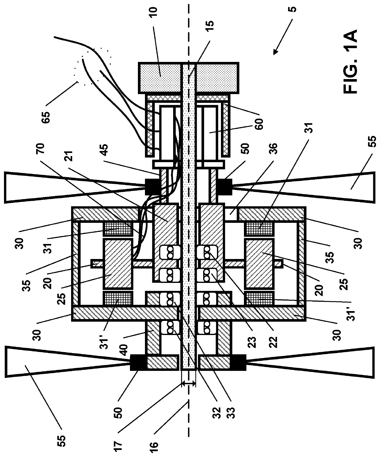
[0049]As shown in FIG. 1, the subject invention comprises a CR axial motor 5 in which a base member 10 is non-rotationally secured to a central shaft 15. Usually, the base 10 and central shaft are fabricated from a metal of metal alloy, however, natural and synthetic polymers, ceramics, glass, and equivalent material are contemplated to be within the realm of this disclosure. Further, the bas 10 and central shaft may be fabricated as a single unit. The central shaft 15 has a long axis 16 with first and second ends and a perpendicular short axis 17. The shaft first end is non-rotationally affixed (either permanently or removably) to the base 10 by standard means such as gluing, set screws, screwing, welding, brazing, soldering, and the like.

[0050]The remainder of the components of subject invention will be configured around the central shaft either in a rotational or non-rotational manner. A first rotational member is mounted by first bearings 22 and 23 to the central shaft 15 around...

embodiment 7

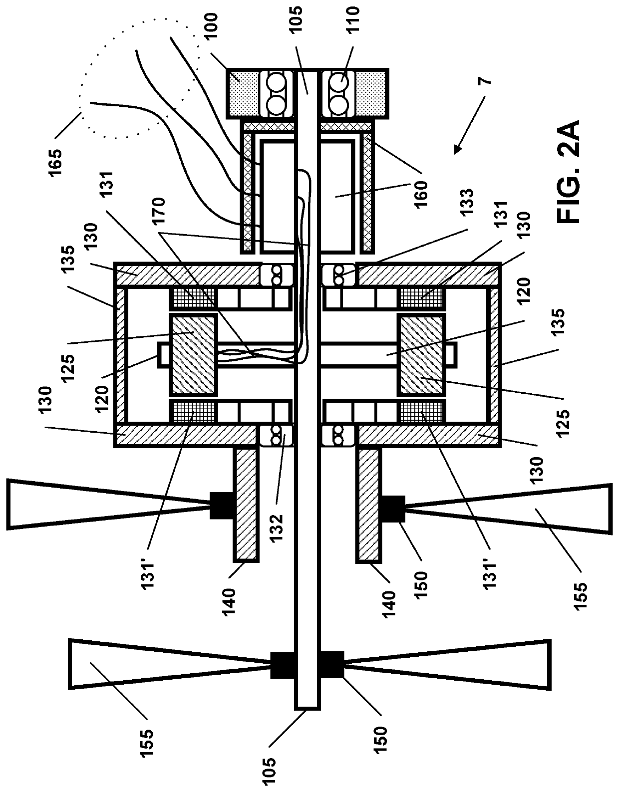
[0060]The second rotational member is mounted by two sets of bearings 132 and 133 on the central shaft 105 and comprises a support housing 130, with two opposing side walls, and an end member 135 that extends between the two support housing 130 side walls. Embodiment 7 has two sets of permanent magnets 131 and 131′ mounted on the inside surfaces of the support housing 130 opposing side walls.

[0061]A first drive member attachment region 141 is located proximate the central shaft's 105 second end. Propeller attachment couplers 150 are secured to the central shaft 105 at the attachment regions 141 and extend into propeller blades 155.

[0062]A second drive member 140 is attaches to and extends from the support housing 130. The second drive member 140 is generally of cylindrical form and is secured to propeller attachment couplers 150 and into propeller blades 155.

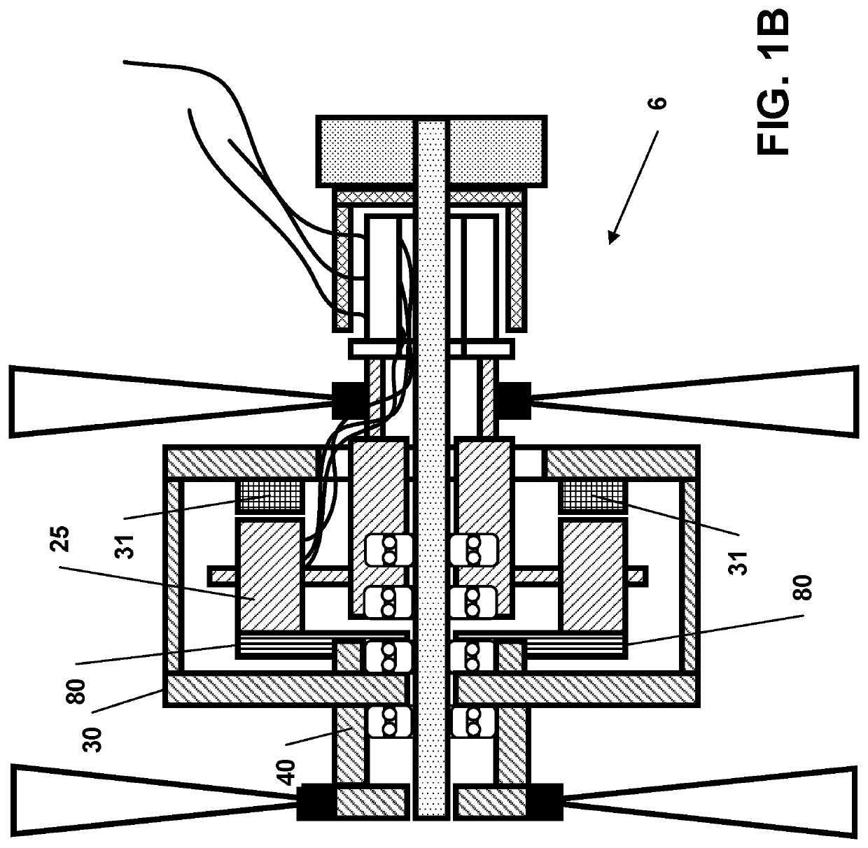
[0063]FIG. 2B shows only one set of permanent magnets 31 and not two sets, on the support housing 130 side walls. A circular p...

experiment # 1

[0072]Experiment #1:

[0073]These tests were conducted with three different types of motors coupled to equal propellers: 1) a standard motor from RC Timer (5010-620KV, found at rctimer.com and most hoppy supply stores) with one propeller; 2) a CR axial motor that is approximately the same size as the standard RC Timer motor (5010-620KV) with one propeller held stationary (this mimics a standard motor); and 3) a CR axial motor that is approximately the same size as the standard RC Timer motor (5010-620KV) with two oppositely spinning propellers. All runs were at 22° C. for the room temperature.

[0074]If we select 22.3 volts and 16.00 amps for both the CR axial motor with only one propeller spinning (the other is held fixed) versus both propellers spinning in opposite directions, the CR axial with both propellers is ˜24% more efficient when comparing motor efficiency in grams per watt (g / W). It is stressed that the protype CR axial motor that was tested was hand-made and will, undoubtedl...


PUM


Abstract

A counter-rotating (CR) axial electric motor assembly is presented, with two oppositely rotating drive members, that is utilized to power any device that has traditionally employed an electric motor to supply rotational power.

Description

CROSS-REFERENCE TO RELATED APPLICATIONS[0001]This application claims priority to, and is a 35 U.S.C. § 111(a) continuation of, PCT international application number PCT / US2020 / 029064 filed on Apr. 21, 2020, incorporated herein by reference in its entirety, which claims priority to, and the benefit of, U.S. provisional patent application Ser. No. 62 / 837,549 filed on Apr. 23, 2019, incorporated herein by reference in its entirety. Priority is claimed to each of the foregoing applications.[0002]The above-referenced PCT international application was published as PCT International Publication No. WO 2020 / 219415 A1 on Oct. 29, 2020, which publication is incorporated herein by reference in its entirety.STATEMENT REGARDING FEDERALLY SPONSORED RESEARCH OR DEVELOPMENT[0003]Not ApplicableNOTICE OF MATERIAL SUBJECT TO COPYRIGHT PROTECTION[0004]A portion of the material in this patent document may be subject to copyright protection under the copyright laws of the United States and of other countr...

Claims


Application Information

Patent Timeline
Patent Type & Authority Applications(United States)
IPC IPC(8): H02K16/00H02K13/00H02K7/00B64D27/24B64C11/48
CPCH02K16/005H02K13/003B64C11/48B64D27/24H02K7/003H02K21/24H02K7/14B64U50/19Y02T50/60H02K16/02B64C27/12
Inventor WISHART, RANDELL J.
Owner CR FLIGHT L L C
Why Eureka
Try Eureka