Apparatus for draining lymph into veins

a technology of lymphatic drainage and apparatus, which is applied in the field of apparatus for draining lymph into veins, can solve the problems of clogging of osmosis membrane and osmosis, and achieve the effect of reducing the number of operations

Pending Publication Date: 2022-05-12
NEW VINCI CO LTD
View PDF10 Cites 0 Cited by
  • Summary
  • Abstract
  • Description
  • Claims
  • Application Information

AI Technical Summary

Benefits of technology

[0007]In view of this, the present invention provides an apparatus for draining lymph into veins to reduce the number of operations or solve problems such as the possible collapse of the built-in battery.
[0009]In addition, one end of the first catheter connects to the chamber space of the chamber, and the other end of the first catheter connects with a vein (about 2-5 mm in diameter) to allow the chamber space of the chamber connecting to the vein. The second sensing element receives a radio wave emitted by a first sensing element of a power supply device to emit an electrical signal. Furthermore, a pump is disposed in the chamber and electrically connects to the second sensing element, wherein the electrical signal emitted by the second sensing element drives the pump to generate a negative pressure in a range between 10 mmHg and 100 mmHg, preferably between 10 mmHg and 50 mmHg, more preferably between 10 mmHg and 30 mmHg, and most preferably between 10 mmHg and 15 mmHg, between 30 mmHg and 50 mmHg or between 50 mmHg and 80 mmHg in the chamber space to make the pressure inside of the chamber space lower than the pressure outside of the chamber space (i.e., tissue pressure), thereby guiding the lymph to permeate into the chamber space from the outside of the chamber space, and the lymph was drained to the vein via the first catheter to achieve the effect of remove the lymph between the tissues.
[0016]In a further aspect of the present invention, the pump may further comprise a second catheter, a second opening may be further formed on the chamber wall of the chamber, and the inlet end is connected with the second opening by the second catheter. Accordingly, one end of the second catheter would connect to the second opening and the other end would connect to the inlet end of the pump, so that the pump does not need to be disposed adjacent to the drainage device. The separation of the pump and chamber can reduce the volume of the drainage device, thereby reducing the discomfort of the patient at the implantation site. However, the present invention is not limited thereto. In addition, in order to respond to the lymphatic drainage conditions of different tissues, the pump of the present invention may be designed as a pressure-adjustable pump, a remote-controllable pump, or a wirelessly-controlled pump, such as a micropump, peristaltic micropump or manual micropump. However, the present invention is not limited thereto. By controlling the pump pressure and speed, the effect of controlling lymph drainage is achieved.
[0017]In the apparatus for draining lymph into veins of the present invention, the drainage device may further comprise an anti-reflux valve, and the anti-reflux valve may be, for example, but not limited to, a single plate type anti-reflux valve or a dual plate type anti-reflux valve. The anti-reflux valve may be disposed on at least one of the second opening, first catheter, and second catheter. For example, a dual plate type anti-flux forms two pieces of semi-curved elastic sheets on the inner wall of the catheter. When the lymph flows to the vein, it can pass through the anti-reflux valve 26, whereas the venous blood would be stopped by the anti-reflux valve 26 when the venous blood flows back from the vein. Thereby, it prevents the apparatus for draining lymph into veins of the present invention from the occurrence of the backflow of venous blood during the drainage process, so that it increases the lymph drainage effect of the apparatus for draining lymph into veins of the present invention.
[0021]In addition, the apparatus for draining lymph into veins of the present invention may get clogged due to the mixing of protein tissues, blood cells, platelets or other substances. Therefore, the drainage device of the present invention may further comprise a drug injection silicone film disposed on the chamber to allow the drug injection silicone film injecting a drug into the chamber space of the chamber. However, the present invention is not limited thereto. Through this silicone film, skin-injected anticoagulant (such as heparin), related drugs (such as fibroblast antibody), or antibiotics are provided to reduce the blood clotting and clogging in the whole lymph drainage apparatus, or reduce the possibility of infection.

Problems solved by technology

The aforementioned osmosis membrane may be made of polymer molecular materials having negative charges for the reason that fibroblasts would attach to the osmosis membrane and form a biomembrane when using an electrically neutral membrane, resulting in the clogging of the osmosis membrane.
In respect of using an osmosis membrane having positive charges, bacteria may attach to the osmosis membrane in the case of infection, resulting in the clogging of the osmosis.

Method used


Image

  • Apparatus for draining lymph into veins
  • Apparatus for draining lymph into veins
  • Apparatus for draining lymph into veins

Examples


embodiment 1

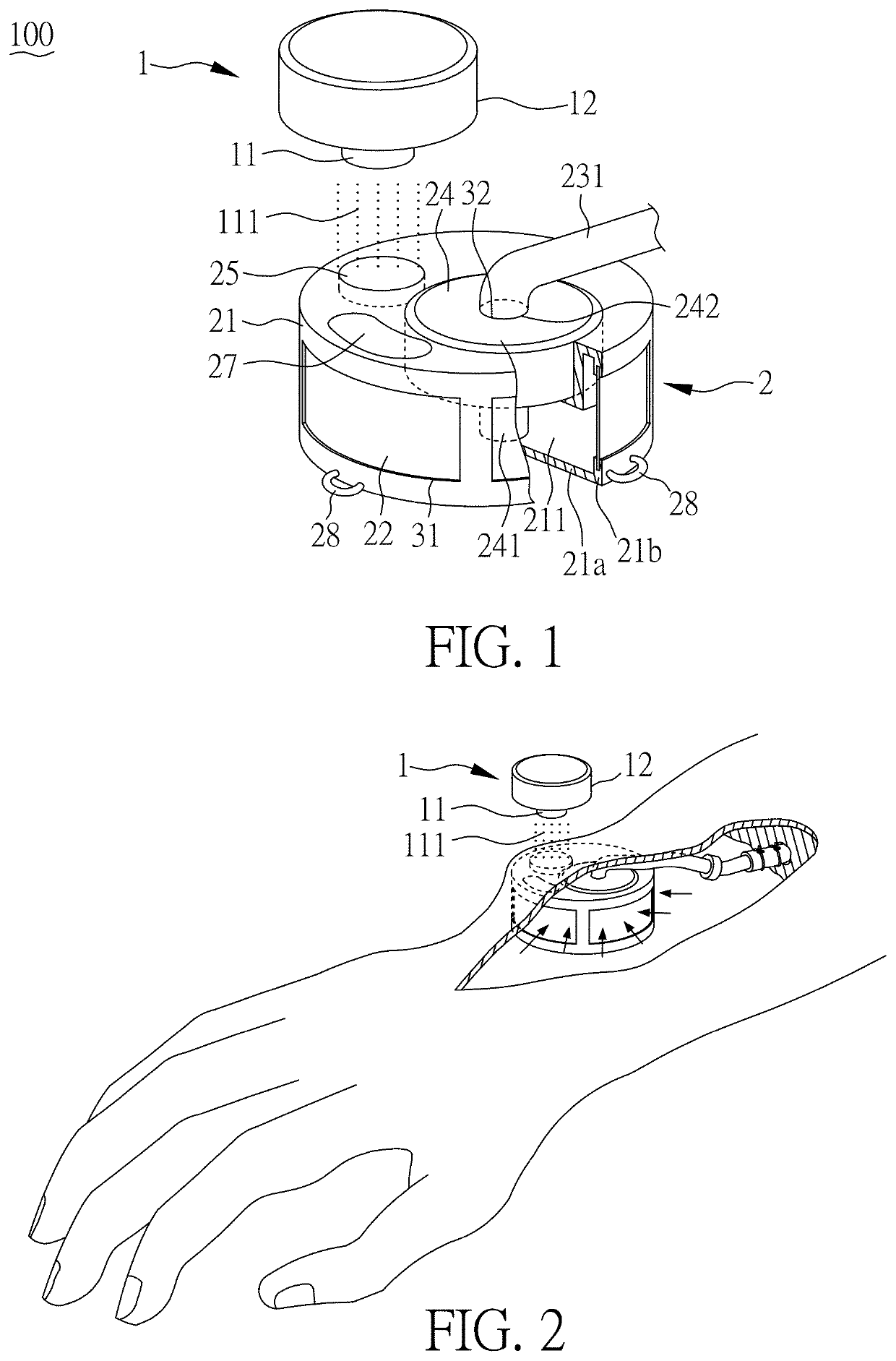
[0037]FIG. 1 shows a partial schematic diagram of an apparatus for draining lymph into veins 100 according to Embodiment 1 of the present invention. FIG. 2 shows a schematic diagram of implantation of an apparatus for draining lymph into veins 100 according to Embodiment 1 of the present invention. FIG. 3 shows a schematic diagram of an apparatus for draining lymph into veins 100 according to Embodiment 1 of the present invention.

[0038]As shown in FIG. 1 to FIG. 3, the apparatus for draining lymph into veins 100 of this embodiment comprises a power supply device 1 and a drainage device 2, wherein the power supply device 1 comprises a first sensing element 11 and a power supply element 12, the power supply element 12 is electrically connected to the first sensing element 11 to supply power to the first sensing element 11. The first sensing element 11 is used to emit a radio wave 111 and is an induction coil. However, the first sensing element 11 is subject to no particular limitation...

embodiment 2

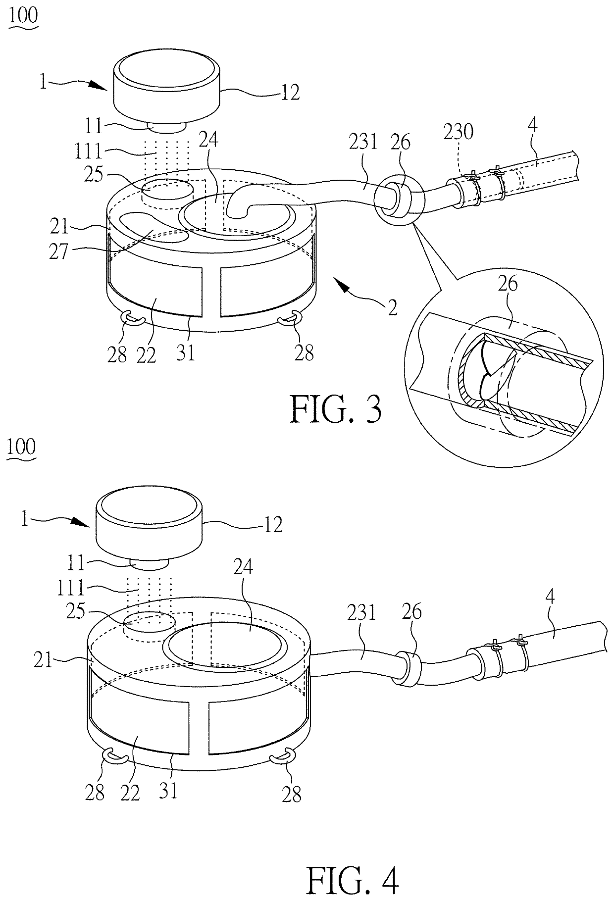
[0045]FIG. 4 shows a schematic diagram of an apparatus for draining lymph into veins according to this embodiment of the present invention.

[0046]As shown in FIG. 4, the configuration of this embodiment is similar to that of Embodiment 1, so that it has similar features and effects as Embodiment 1. Therefore, such descriptions are omitted. The difference from Embodiment 1 lies in the first catheter 231 being disposed on the lateral side of the chamber 21. In addition, the apparatus for draining lymph into veins 100 does not have a drug injection silicone film 27 (as shown in FIG. 3). In addition, as long as it is reasonable, the detailed features of the embodiments can also be combined arbitrarily.

embodiment 3

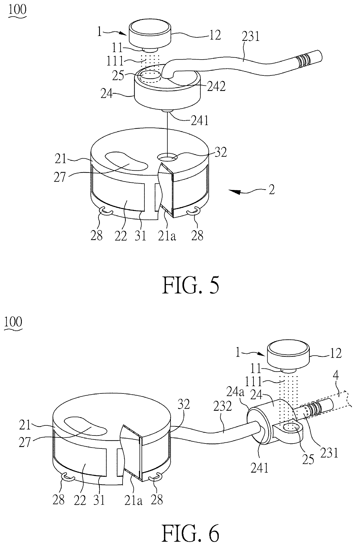
[0047]FIG. 5 shows a schematic diagram of an apparatus for draining lymph into veins 100 according to Embodiment 3 of the present invention.

[0048]As shown in FIG. 1 and FIG. 5, the configuration of this embodiment is similar to that of Embodiment 1, so that it has similar features and effects as Embodiment 1. Therefore, such descriptions are omitted. The differences from Embodiment 1 are the lack of anti-reflux valve 26 (as shown in FIG. 3) and the positions of the pump 24 and the second sensing element 25. In Embodiment 1, the pump 24 is disposed in the chamber 21 and the second sensing element 25 is also disposed in the chamber 21 directly. However, in the present embodiment, the pump 24 is disposed outside of the chamber 21 and adjacent to the chamber 21, in which the pump 24 is a micropump (but not limited thereto); the inlet end 241 of the pump 24 is connected with the second opening 32 formed on the chamber wall 21a; the outlet end 242 of the pump 24 is connected with the firs...


PUM


Abstract

An apparatus for draining lymph into vein includes a drainage device. The drainage device includes a chamber, an osmosis membrane, a first catheter, a second sensing element, and a pump. The chamber includes a chamber wall, wherein a chamber space is formed by the chamber wall, and a first opening is formed on the chamber wall. The osmosis membrane disposed on the first opening. One end of the first catheter connects to the chamber space, and the other end of the first catheter connects with a vein. The second sensing element receives a radio wave emitted by a first sensing element of a power supply device to send an electrical signal. The pump is disposed in the chamber and connecting to the second sensing element, wherein a negative pressure in the chamber space is generated by the pump to drain lymph into the vein via the first catheter.

Description

CROSS REFERENCE TO RELATED APPLICATION[0001]This application claims the benefits of the Taiwan Patent Application Serial Number 109139556, filed on Nov. 12, 2020, the subject matter of which is incorporated herein by reference.BACKGROUND OF THE INVENTION1. Field of the Invention[0002]The present invention relates to an apparatus for draining lymph into veins and, more particularly, to a novel apparatus for draining lymph suitable for effectively relieving lymphedema.2. Description of Related Art[0003]Lymphedema refers to swelling caused by the accumulation of excessive lymph in body tissues. Under normal circumstances, 10% of the arterial blood exuded from the capillaries contains protein-rich lymph that flows through the lymphatic vessels to the lymph nodes, and flows back to the veins in the end. However, under conditions that the proximal lymph nodes are surgically removed, or that the function of the remaining lymph nodes is destroyed due to radiotherapy, or that the lymphatic s...

Claims


Application Information

Patent Timeline
Patent Type & Authority Applications(United States)
IPC IPC(8): A61M1/00A61M39/24
CPCA61M1/009A61M2205/04A61M2205/8206A61M39/24A61M27/002A61M2205/82A61M2202/0405A61M1/80A61F2/2476A61M2205/8243A61M1/962
Inventor CHENG, MING-HUEI
Owner NEW VINCI CO LTD
Why Eureka
Try Eureka