Optical phase array antenna based on optical waveguide having double grating structure and lidar including the same

a phase array antenna and optical waveguide technology, applied in waveguides, antennas, instruments, etc., can solve the problems of limited power and weight, large amount of power, and inability to use, and achieve the effects of improving transmittance and directivity, light and cheaper, and mass production

Pending Publication Date: 2022-05-19
GWANGJU INST OF SCI & TECH
View PDF0 Cites 2 Cited by
  • Summary
  • Abstract
  • Description
  • Claims
  • Application Information

AI Technical Summary

Benefits of technology

[0013]First, the present disclosure is directed to an optical phase array antenna structure designed to develop a light detection and ranging (LiDAR) sensor, which is configured for autonomous driving based on an optical phase array antenna and an unmanned flight vehicle, replace mechanical rotation according to the related art, is lighter and cheaper, and is mass-producible.
[0014]Second, the present disclosure is directed to an optical phase array antenna structure having improved transmittance and directivity compared with the related art.
[0015]Third, the present disclosure is directed to an optical phase array antenna structure that may be produced by complementary metal-oxide semiconductor (CMOS) semiconductor process technology, have a maximum output of 2 W or more, and increase a noise-to-signal ratio through modification of a structure of an optical phase array antenna satisfying a viewing angle of 120°.

Problems solved by technology

However, an existing mechanical LiDAR includes a rotating motor that is heavy in weight and consumes a large amount of power and thus cannot be used in an unmanned flight vehicle requiring limited power and weight, and a mechanical rotational speed thereof does not correspond to a rotational speed required for driving of an autonomous vehicle on an express way.
In order to increase a maximum distance to be measured by the LiDAR, an antenna requires a higher laser output but a silicon waveguide having low laser threshold power and high linear or nonlinear loss is disadvantageous compared to a silicon nitride waveguide.
In order to increase a limited horizontal viewing angle of an optical phase array antenna, a distance between antenna elements should be close to a distance corresponding to half a wavelength (λ / 2), but as the distance between the antenna elements becomes shorter, a desired output phase distribution can be more difficult to achieve due to crosstalk between the antenna elements.
In the case of a LiDAR designed to be mounted in an autonomous vehicle, the LiDAR should be operated normally regardless of a temperature change (−40° C. to 85° C.) in the autonomous vehicle for the safety of passengers and pedestrian safety and thus it is difficult to use a phase change through local heating of a silicon nitride waveguide.
Due to a process performed on a wafer, in a flat optical element, the directivity of a laser output from a chip is difficult to achieve due to a vertical refractive index symmetry, and therefore, laser beams output isotropically are reflected from a bottom surface of the flat optical element and thus interfere with laser beams traveling upward, thereby causing a change of a propagation direction of output laser beams and generating noise.

Method used


Image

  • Optical phase array antenna based on optical waveguide having double grating structure and lidar including the same
  • Optical phase array antenna based on optical waveguide having double grating structure and lidar including the same
  • Optical phase array antenna based on optical waveguide having double grating structure and lidar including the same

Examples


Embodiment Construction

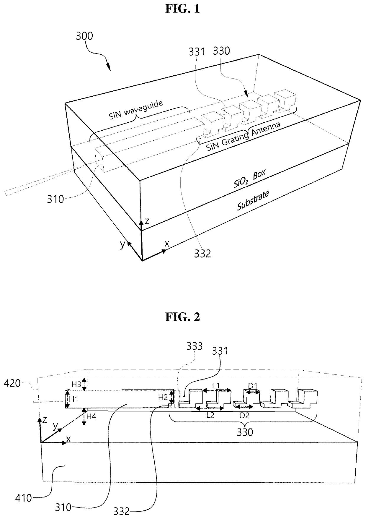
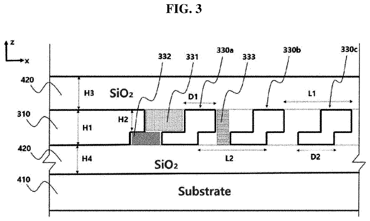
[0046]Hereinafter, an optical phase array antenna employing an optical waveguide having a double grating structure according to the present disclosure will be described with reference to the accompanying drawings. As used herein, ‘one direction’ is illustrated as an ‘X-axis direction’ in the drawings and should be understood to mean a longitudinal direction of an optical phase array antenna according to the present disclosure. In the drawings, ‘width direction’ is illustrated as a ‘Y-axis direction’ and a ‘height direction’ is illustrated as a ‘Z-axis direction’. However, the directions defined herein are defined merely for convenience of understanding and thus the present disclosure is not limited thereby.

[0047]An optical phase array antenna according to the present disclosure will be described with reference to FIGS. 1 to 3, and components thereof will be described in conjunction with FIGS. 7 and 8.

[0048]The optical phase array antenna according to the present disclosure includes ...


PUM

PropertyMeasurementUnit
viewing angleaaaaaaaaaa
temperatureaaaaaaaaaa
thicknessaaaaaaaaaa

Abstract

Provided is an optical phase array antenna including a coupling part configured to receive light from a laser generator, an optical distributor configured to distribute the light transmitted from the coupling part to a plurality of antenna element waveguides, a phase modulator configured to modulate a phase of the light transmitted through the plurality of antenna element waveguides, and a light outputter configured to output the light modulated by the phase modulator, the light outputter including the plurality of antenna element waveguides extending in one direction, wherein each of the plurality of antenna element waveguides includes a double grating antenna part in which a downward-curved portion curved downward from an upper surface and an upward-curved portion curved upward from a lower surface are repeatedly formed in the one direction.

Description

CROSS-REFERENCE TO RELATED APPLICATION[0001]This application claims priority to and the benefit of Korean Patent Application No. 2020-0156049, filed on Nov. 19, 2020, the disclosure of which is incorporated herein by reference in its entirety.BACKGROUND1. Field of the Invention[0002]The present disclosure relates to an optical phase array antenna employing an optical waveguide having a double grating structure, and a light detection and ranging (LiDAR) including the same.2. Discussion of Related Art[0003]A light detection and ranging (LiDAR) sensor for use in an autonomous vehicle measures a time required to receive a reflected pulse laser beam when a pulse laser beam is incident on an object so as to obtain three-dimensional (3D) spatial information. Laser emission methods are largely divided into a “flash method” and a “scanning method”. The flash method is a method of simultaneously injecting laser beams into a wide area, in which a light-receiving element is in a two-dimensional...

Claims


Application Information

Patent Timeline
Patent Type & Authority Applications(United States)
IPC IPC(8): G01S7/481G02F1/295
CPCG01S7/4814G02F1/2955G01S7/4817H01Q3/2676G01S7/4861G01S7/484H01P3/08
Inventor YU, NAN EIPARK, BYEONG CHAN
Owner GWANGJU INST OF SCI & TECH
Why Eureka
Try Eureka