Process and device for vaporizing purge liquid from a cryogenic liquid vaporizer

Pending Publication Date: 2022-05-26
LAIR LIQUIDE SA POUR LETUDE & LEXPLOITATION DES PROCEDES GEORGES CLAUDE
View PDF0 Cites 1 Cited by
  • Summary
  • Abstract
  • Description
  • Claims
  • Application Information

AI Technical Summary

Benefits of technology

[0048]The invention consists in rapidly vaporizing the entire liquid purge, to obtain a gas at ambient temperature, easily measure its flow rate and take a gaseous sample to be sent continuously to impurity analysers. The remaining gas is not analysed and is then mixed with the production

Problems solved by technology

When dealing with the analysis of low-volatility impurities, the difficulty lies in obtaining a vaporized sample at ambient temperature, which is as representative as possible of the liquid to be analysed.
Thus, they may lead to a problem of representativeness of the sample taken, in particular as regards the capillary sampling.
This is because the latter, if it is connected to a liquid bath

Method used


Image

  • Process and device for vaporizing purge liquid from a cryogenic liquid vaporizer
  • Process and device for vaporizing purge liquid from a cryogenic liquid vaporizer

Examples


Embodiment Construction

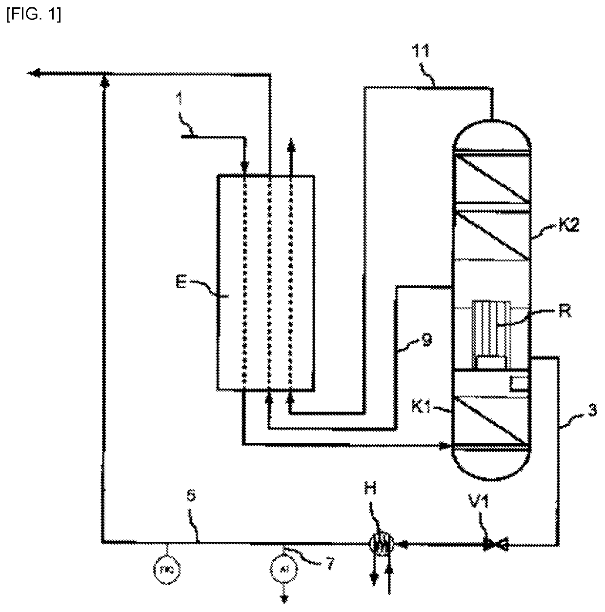
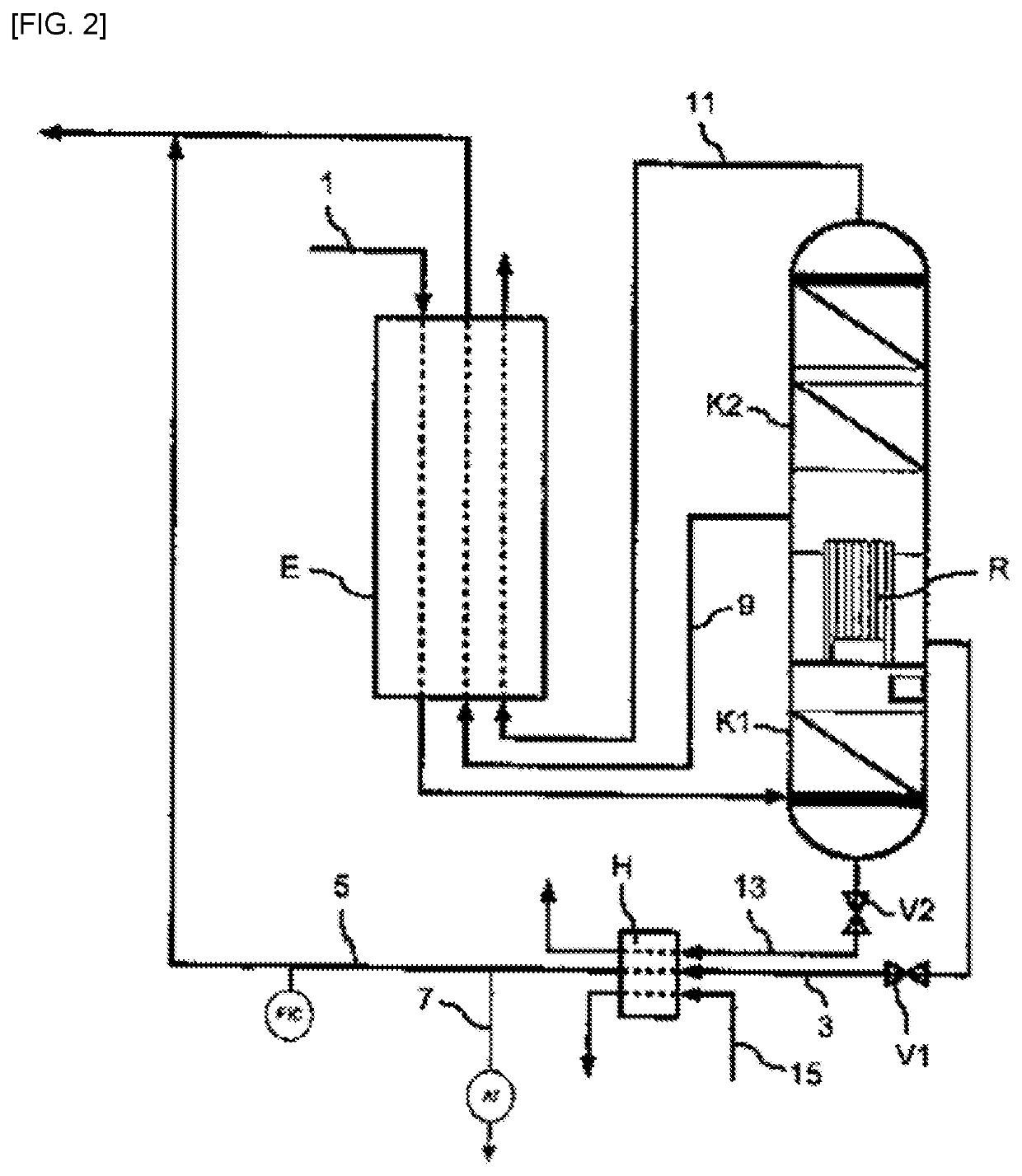
[0053]In [FIG. 1] the device for separating air by cryogenic distillation is constituted by a main heat exchanger E and a double column K1, K2, inside one or more insulated chambers, for example a vacuum insulated cold box, enabling operation at cryogenic temperatures.

[0054]The double column comprises a first column K1, surmounted by a second column K2 operating at a lower pressure than the first column.

[0055]Air 1 is cooled in the exchanger E and is sent to the bottom of the first column K1 where it is separated by distillation. An oxygen-enriched flow is sent from the bottom of the first column K1 an intermediate point of the column K2. A nitrogen-enriched flow is sent from the top of the first column Kl to the second column K2.

[0056]The nitrogen from the top of the first column is condensed in the vaporizer-condenser R at the bottom of the second column where it is used to vaporize the bottom liquid of the second column which surrounds the vaporizer R. A flow of gaseous oxygen 9 ...


PUM


Abstract

Process for vaporizing purge liquid from a cryogenic liquid vaporizer, the liquid containing at least one impurity, in which the purge liquid is withdrawn from a bath of liquid surrounding the vaporizer or resulting from the vaporizer, all of the purge liquid is vaporized in a heater, characterized in that the content of the at least one impurity in at least one portion, or even all of the heated vaporized liquid is analysed and the flow rate of at least one portion, or even all of the heated vaporized liquid is measured.

Description

CROSS REFERENCE TO RELATED APPLICATIONS[0001]This application claims the benefit of priority under 35 U.S.C. § 119 (a) and (h) to French patent application No. FR 2012162, filed Nov. 26, 2020, the entire contents of which are incorporated herein by reference.FIELD OF THE INVENTION[0002]The present invention relates to a process and to a device for vaporizing purge liquid from a cryogenic liquid vaporizer.BACKGROUND OF THE INVENTION[0003]A cryogenic liquid vaporizer partially vaporizes a liquid containing impurities in order to form a gas. At cryogenic temperatures, some of these impurities are liable to be deposited in the constituent components of the air separation units, in particular in the vaporizer-condenser of the distillation columns. Knowledge of the content of impurities is therefore essential, both in terms of product quality and plant safety.[0004]Such cryogenic liquids, which are usually oxygen, nitrogen or else argon, have a temperature below around −170° C. They are i...

Claims


Application Information

Patent Timeline
IPC IPC(8): G01N1/44F17C7/04
CPCG01N1/44F17C7/04F17C2223/0161F17C2265/015F17C2221/011F17C2227/0302F17C2250/0443F17C9/02F17C13/00F17C13/023F17D1/005F17D3/01B01D3/14G01N1/14F17C2201/0109F17C2205/0323F17C2227/0304F17C2227/039G01N2001/149F25J3/0486F25J3/04412F25J3/04824F25J3/04769F25J2280/02F25J2250/02F25J2250/50F25J2250/52F25J2245/50F25J3/04284F25J2240/02F25J3/04866
Inventor DAVIDIAN, BENOIT
Owner LAIR LIQUIDE SA POUR LETUDE & LEXPLOITATION DES PROCEDES GEORGES CLAUDE
Why Eureka
Try Eureka