Communication device, base station device, communication method, and base station device control method

a communication device and control method technology, applied in the direction of spatial transmit diversity, electrical apparatus, diversity/multi-antenna systems, etc., can solve the problems of low throughput, data reception (i.e. decoding) on the receiving side, and the method might not be adopted in cellular radio communication systems, so as to reduce unnecessary signal processing

Pending Publication Date: 2022-05-26
SONY CORP
View PDF6 Cites 3 Cited by
  • Summary
  • Abstract
  • Description
  • Claims
  • Application Information

AI Technical Summary

Benefits of technology

[0005]In view of this, the present disclosure proposes a communication device, a base station device, a communication method, and a base station device control method capable of reducing unnecessary signal processing.

Problems solved by technology

The former method might not be adopted in cellular radio communication systems (for example, 5G) because of the computational cost of generating a beam each time.
On the other hand, adoption of a modulation method capable of transmitting a large amount of bits, such as 256 Quadrature Amplitude Modulation (QAM) even with poor channel quality would lead to a failure in data reception (i.e. decoding) on the receiving side, resulting in a low throughput as well.
Reporting this measurement result can be a significant amount of overhead.
Unfortunately, however, the fully digital architecture has a drawback of enlargement of the digital circuit.
However, when there are two beams using such an antenna panel, the terminal device 200 cannot determine how to select the antenna panel and the beam.
However, there are cases where there is no instruction from the base station 100 or the setting of the instruction by the base station 100 is not in time, which leads to the necessity of performing a process for such a case.
However, when synchronization signals (reference signals) are provided from different antenna panels of the base station 100, it is difficult to determine which antenna panel and beam used in reception of which synchronization signal should be used as the default.
That is, in the prior technology, the signal group has been transmitted without considering the arrangement of the antenna panels on the base station side, leading to a concern of occurrence of unnecessary reception processes on the terminal side.

Method used


Image

  • Communication device, base station device, communication method, and base station device control method
  • Communication device, base station device, communication method, and base station device control method
  • Communication device, base station device, communication method, and base station device control method

Examples


application examples

4. APPLICATION EXAMPLES

[0188]The technology according to the present disclosure is applicable to various products.

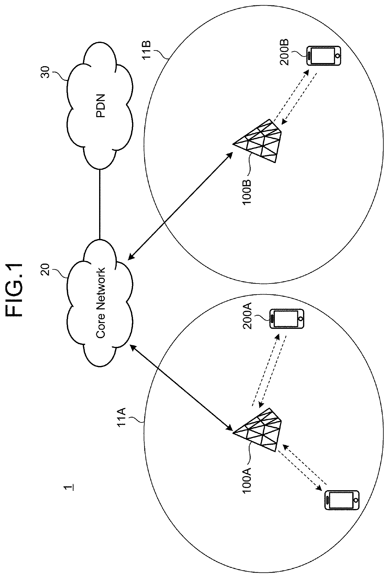
[0189]For example, the base station 100 may be any of eNodeB, ng-eNodeB, gNodeB, or en-gNodeB as described above. In addition to or instead of this, the base station 100 may be referred to as EUTRAN when the base station 100 is either eNodeB or en-gNodeB. In addition to or instead of this, the base station 100 may be referred to as NGRAN when the base station 100 is either gNodeB or ng-eNodeB. Furthermore, the base station 100 may be a Master Node (MN) or a Secondary Node (SN) in Dual Connectivity. That is, the base station 100 may be a Secondary gNodeB in the case of EUTRA-NR Dual Connectivity or in the case of NR-NR Dual Connectivity. In this case, a part or all of the above-described RRC signaling may be transmitted to and received from the UE (terminal device 200) via the MN, or may be directly transmitted or received between the UE (terminal device 200) and a second...

first application example

[0210]FIG. 20 is a block diagram illustrating an example of a schematic configuration of a smartphone 900 to which the technology according to the present disclosure is applicable. The smartphone 900 includes a processor 901, memory 902, storage 903, an external connection interface 904, a camera 906, a sensor 907, a microphone 908, an input device 909, a display device 910, a speaker 911, a radio communication interface 912, one or more antenna switches 915, one or more antennas 916, a bus 917, a battery 918, and an auxiliary controller 919.

[0211]The processor 901 may be a CPU or a System on Chip (SoC), for example, and controls the functions of the application layer and other layers of the smartphone 900. The memory 902 includes RAM and ROM and stores programs to be executed by the processor 901, and data. The storage 903 may include a storage medium such as semiconductor memory or a hard disk. The external connection interface 904 is an interface for connecting an external device...

second application example

[0222]FIG. 21 is a block diagram illustrating an example of a schematic configuration of a car navigator 920 to which the technology according to the present disclosure is applicable. The car navigator 920 includes a processor 921, memory 922, a Global Positioning System (GPS) module 924, a sensor 925, a data interface 926, a content player 927, a storage medium interface 928, an input device 929, a display device 930, a speaker 931, a radio communication interface 933, one or more antenna switches 936, one or more antennas 937, and a battery 938.

[0223]The processor 921 may be a CPU or SoC, for example, and controls the navigation function and other functions of the car navigator 920. The memory 922 includes RAM and ROM and stores programs to be executed by the processor 921, and data.

[0224]The GPS module 924 measures the position (including latitude, longitude, and altitude) of the car navigator 920 using GPS signals received from GPS satellites. The sensor 925 can include a group ...


PUM


Abstract

A communication device (200) includes an acquisition unit (242) and a reception unit (243). The acquisition unit (242) acquires similarity information indicating the similarity of the beam characteristics of the transmitting antenna panel in a plurality of signal groups transmitted from a base station (100). The reception unit (243) selects and receives a signal group to be received, from among the plurality of signal groups, based on the similarity information acquired by the acquisition unit (242).

Description

FIELD[0001]The present disclosure relates to a communication device, a base station device, a communication method, and a base station device control method.BACKGROUND[0002]Various radio access methods and radio networks in cellular mobile communications (hereinafter, also referred to as “Long Term Evolution (LTE)”, “LTE-Advanced (LTE-A)”, “LTE-Advanced Pro (LTE-A Pro)”, “Fifth generation (5G)”, “New Radio (NR)”, “New Radio Access Technology (NRAT)”, “Evolved Universal Terrestrial Radio Access (EUTRA)”, or “Further EUTRA (FEUTRA)”) are under examination in 3rd Generation Partnership Project (3GPP). In the following description, LTE includes LTE-A, LTE-A Pro, and EUTRA, and NR includes NRAT and FEUTRA. In LTE and NR, a base station device (base station) is also referred to as an evolved Node B (eNodeB) in LTE and referred to as gNodeB in NR, while a terminal device (mobile station, mobile station device, or terminal) is also referred to as User Equipment (UE). LTE and NR are cellular...

Claims


Application Information

Patent Timeline
Patent Type & Authority Applications(United States)
IPC IPC(8): H04B7/08H04W16/28H04W8/22H04W48/16
CPCH04B7/088H04W16/28H04B7/0874H04W48/16H04W8/22H04B7/0695H04B7/0404H04W8/24H04W48/20
Inventor TAKANO, HIROAKI
Owner SONY CORP
Why Eureka
Try Eureka