TIG Welding Flux for Dissimilar Steels

a technology of dissimilar steels and fluxes, applied in the field of welding fluxes, can solve the problems of increasing welding time and manufacturing costs, and cannot be carried out on site, and achieve the effects of easy spread, easy melting, and great uniformity

Active Publication Date: 2022-06-16
NAT PINGTUNG UNIV OF SCI & TECH
View PDF5 Cites 0 Cited by
  • Summary
  • Abstract
  • Description
  • Claims
  • Application Information

AI Technical Summary

Benefits of technology

[0009]Accordingly, the TIG welding flux for dissimilar steels can be used with TIG welding procedure, and thus the two workpieces can be jointed on site, improving the application flexibility of the TIG welding flux for dissimilar steels. Moreover, the TIG welding flux for dissimilar steels can be used with TIG welding procedure, forming a two jointed workpieces by a stainless steel workpiece and a carbon steel workpiece. The weld bead between the stainless steel workpiece and the carbon steel workpiece has a weld D / W ratio (weld depth / bead width ratio) more than or equal to 0.9. Therefore, for thicker workpieces (such as that with a thickness above 3 mm), the formation of bevel faces of the two workpieces can also be omitted, solving the problems such as the decrease of mechanical strength and the large heat-affected zone (HAZ). In addition, omitting the formation of the bevel faces of the two workpieces can also reduce welding time and manufacturing costs.
[0011]In preferred form shown, the TIG welding flux for dissimilar steels has a plurality of powdered particles each having a diameter of 50-90 μm. With such performance, the plurality of powdered particles can form a homogeneous mixture with great uniformity. As such, the TIG welding flux for dissimilar steels can be easily spread on the surfaces of the two workpieces. Also, the TIG welding flux for dissimilar steels can be easily melted by a heat source, and the weld depth can therefore be increased.

Problems solved by technology

However, the FSW procedure is carried out by utilizing a specialized machine, and thus cannot be carried out on site.
Moreover, the bevel faces of the stainless steel workpiece and the carbon steel workpiece should be formed at first, thus increasing welding time and manufacturing costs.

Method used


Image

  • TIG Welding Flux for Dissimilar Steels
  • TIG Welding Flux for Dissimilar Steels

Examples


Embodiment Construction

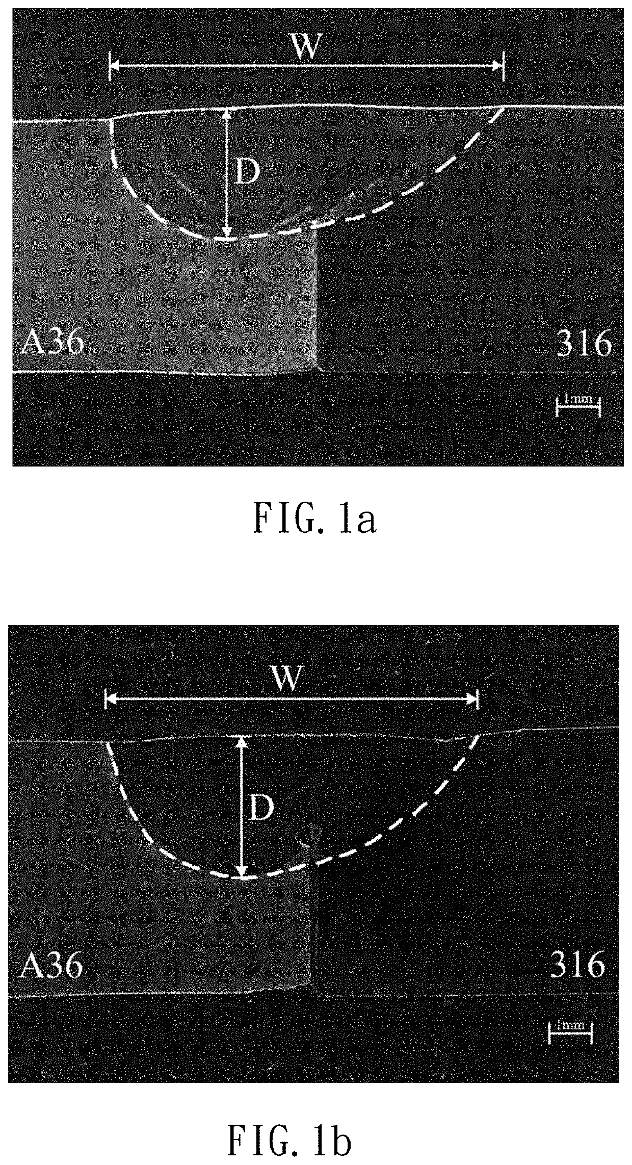
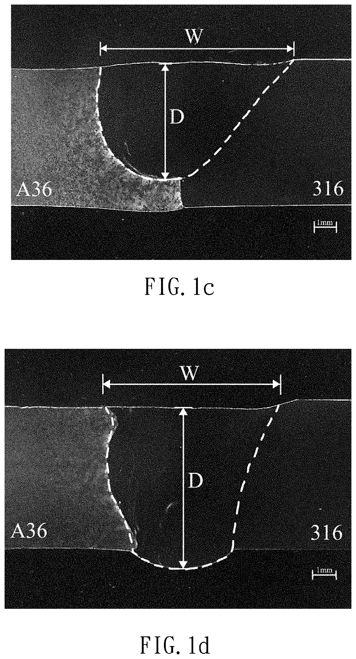
[0017]A TIG welding flux for dissimilar steels according to a specific embodiment of the present invention that can be used with tungsten inert gas (TIG) welding procedure to join a stainless steel workpiece and a carbon steel workpiece.

[0018]Specifically, the stainless steel workpiece can be made of ASTM 316 stainless steel with chemical components shown in TABLE 1. The carbon steel workpiece can be made of ASTM A36 carbon steel with chemical components shown in TABLE 2. However, the stainless steel workpiece and the carbon steel workpiece can be made of by other known stainless steel and carbon steel, respectively, which can be appreciated by a person having ordinary skill in the art.

TABLE 1CSiMnPSNiCrMoFewt≤0.08≤0.75≤2≤0.045≤0.0310-1416-182-3Bal.%

TABLE 2CSiPSCuFewt %≤0.25≤0.40≤0.04≤0.05≥0.20Bal.

[0019]The TIG welding flux for dissimilar steels can include silicon dioxide (SiO2), cobalt (II, III) oxide (Co3O4), manganese (II, III) oxide (Mn3O4), nickel (III) oxide (Ni2O3), molybden...


PUM

PropertyMeasurementUnit
diameteraaaaaaaaaa
thicknessaaaaaaaaaa
thicknessaaaaaaaaaa

Abstract

A TIG welding flux for dissimilar steels is used to solve the problem that the conventional friction stir welding procedure for butt-joint welding a stainless steel workpiece and a carbon steel workpiece cannot be used on site, as well as the problem that the increased operating time and manufacturing cost due to forming bevel faces on both the stainless steel workpiece and the carbon steel workpiece. The TIG welding flux for dissimilar steels includes 25-35 wt % of silicon dioxide (SiO2), 20-30 wt % of cobalt (II, III) oxide (Co3O4), 15-20 wt % of manganese (II, III) oxide (Mn3O4), 10-15 wt % of nickel (III) oxide (Ni2O3), 7-12 wt % of molybdenum trioxide (MoO3), 6-11 wt % of manganese (II) carbonate (MnCO3), 5-10 wt % of nickel (II) carbonate (NiCO3), and 2-4 wt % of aluminum fluoride (AlF3).

Description

CROSS REFERENCE TO RELATED APPLICATIONS[0001]The application claims the benefit of Taiwan application serial No. 109144291, filed Dec. 15, 2020, the entire contents of which are incorporated herein by reference.BACKGROUND OF THE INVENTION1. Field of the Invention[0002]The present invention generally relates to a welding flux and, more particularly, to a tungsten inert gas (TIG) welding flux for dissimilar steels.2. Description of the Related Art[0003]Welding of dissimilar steels is the procedure that joining two or more steel workpieces with different chemical components. Due to the significant differences of physicochemical and mechanical properties between the steel workpieces, a specialized welding procedure is needed.[0004]As an example, China patent No. 103600167 discloses a butt-joint welding procedure for a stainless steel workpiece and a carbon steel workpiece. A side of the stainless steel workpiece and a side of the carbon steel workpiece are first milled to form bevel fac...

Claims


Application Information

Patent Timeline
Patent Type & Authority Applications(United States)
IPC IPC(8): B23K35/36B23K35/362
CPCB23K35/3602B23K35/362C22C38/58C22C38/60
Inventor TSENG, KUANG-HUNG
Owner NAT PINGTUNG UNIV OF SCI & TECH
Why Eureka
Try Eureka