Telescoping atherectomy device

a technology of atherectomy device and telescopic body, which is applied in the field oftelescoping atherectomy device, can solve the problems of ripping the vessel wall, affecting the performance of state-of-the-art atherectomy device, and forming scar tissue, so as to and reduce the burden of plaqu

Pending Publication Date: 2022-06-23
ALTAI MEDICAL TECH
View PDF0 Cites 0 Cited by
  • Summary
  • Abstract
  • Description
  • Claims
  • Application Information

AI Technical Summary

Benefits of technology

[0008]Atherectomy devices, and methods of using them are provided, namely devices and methods that (i) can effectively cut and remove the 4 different types of plaque tissue, namely calcified and hard, necrotic and soft, fibrotic, and a combination thereof; (ii) can render a concentric vessel lumen with minimal plaque burden; (iii) can safely self-collect and remove plaque particles to avoid release of emboli; (iv) can effectively treat a blood vessel with a reduced risk of suffering vessel injuries that can lead to increased restenosis; and, importantly, (v) can also handle tight or tough lesions having little to no luminal opening in the lesion. The atherectomy devices taught herein can be telescoping, self-driving, lateral pushing, or a combination thereof.
[0019]In some embodiments, the lateral pushing member can have a proximal end, a distal end, a collapsed state, and an expanded state, the proximal end having an operable connection with the flexible sheath, and the distal end having an operable connection with the cutter. In some embodiments, the operable connection with the flexible sheath and the operable connection with the cutter can each be configured to receive an axial force (i) applied along the axis of the flexible drive shaft from the cutter to the flexible sheath and (ii) transferred through the lateral pushing member during the collapse and the expansion of the lateral pushing member with the reversible telescoping of the flexible drive shaft from the flexible sheath. And, in some embodiments, the operable connection with the cutter can be configured as a rotatably translatable connection to facilitate a rotation of the cutter and the flexible drive shaft without rotating the lateral pushing member during operation of the atherectomy device.

Problems solved by technology

However, such traditional treatments can stretch the artery and induce scar tissue formation, while the placement of a stent may also cut arterial tissue and induce scar tissue formation.
Moreover, the dilatation with the balloon can also rip the vessel wall.
Unfortunately, the art suffers performance limitations in state-of-the-art atherectomy devices.
For example, current devices with rotating cutters cannot handle the variety of soft, fibrous and calcific plaque effectively, either not cutting all types of plaque or breaking up the plaque into large pieces that remain in the arterial bed as emboli that can clog blood vessels downstream.
Calcified plaque can be hard as a bone; fatty plaque is typically soft; and fibrotic plaque is typically viscoelastic, stretchy yet firm, and thus difficult to cut.
Some state-of-the-art devices have burrs that can grind-away hard plaque but can't cut soft or viscoelastic plaque.
Worse yet, they can loosen debris that can become dangerous emboli.
Some state-of-the-art devices have a sharp cutter that can be deflected against one side of the vessel to do eccentric cutting, which is desirable, but the amount of deflection can't be effectively controlled.
And, some state-of-the-art devices have a “nose cone” that prevents the cutter from cutting through lesion that doesn't allow enough progression of the device to reach the cutter blades.
Most importantly, however, is that patients having “tight” or “tough” lesions are currently unable to receive treatments with balloons, stents, or atherectomy devices.
Such lesions are occlusions that leave only a very small luminal opening, or no opening, making it difficult-to-impossible to achieve passage of a guidewire, much less passage of a balloon or stent on the guidewire.
And, as noted above, current atherectomy devices have a difficult time cutting away the plaque, even if the guidewire might be able to pass through the luminal opening.

Method used


Image

  • Telescoping atherectomy device
  • Telescoping atherectomy device
  • Telescoping atherectomy device

Examples


Embodiment Construction

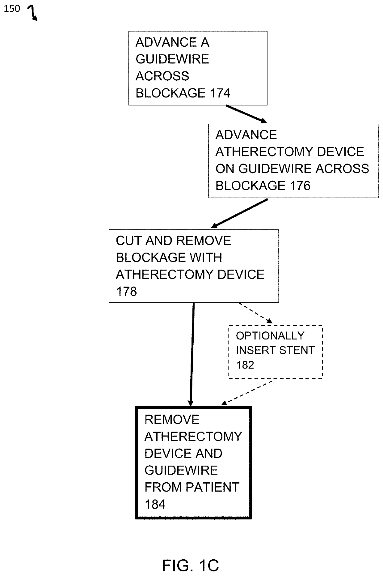
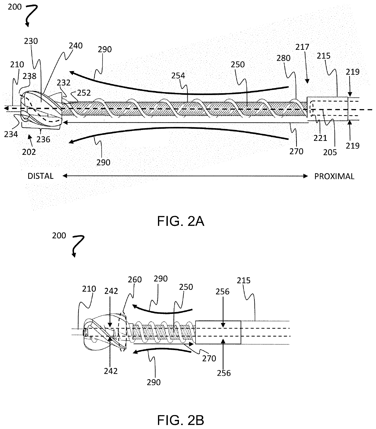
[0031]Atherectomy devices, and methods of using them are provided, namely devices and methods that (i) can effectively cut and remove the 4 different types of plaque tissue, namely calcified and hard, necrotic and soft, fibrotic, and a combination thereof, including fibrocalcific tissue; (ii) can render a concentric vessel lumen with minimal plaque burden; (iii) can safely self-collect and remove plaque particles to avoid release of emboli; (iv) can effectively treat a blood vessel with a reduced risk of suffering vessel injuries that can lead to increased restenosis. And, importantly, one of skill will certainly appreciate an atherectomy device that, surprisingly, (v) can also handle tight or tough lesions having little to no luminal opening in the lesion. The atherectomy devices taught herein can be telescoping, self-driving, lateral pushing, or a combination thereof. The devices provided herein can, for example, render a concentric lumen with minimal plaque burden (<30% vessel di...


PUM


Abstract

Telescoping, self-driving, and laterally-pushing atherectomy devices are provided, each having a flexible sheath, a cutter with helical flutes, and a drive assembly. The drive assembly can have a flexible driveshaft that is rotatably translational with the lumen of the flexible sheath, a positive displacement pump that begins pumping at the distal end of the drive shaft adjacent to the helical flutes at the proximal end of the cutter, and the flexible drive shaft can be longer than the flexible sheath to enable a reversible telescoping of the drive assembly from the lumen of the flexible sheath. The positive displacement pump can be a screw pump having a drive screw portion extending beyond the flexible sheath, exposed for contact with a vascular lumen for the self-driving. And, the devices can have a reversibly-expandable, lateral pushing member at the distal end of the flexible sheath for the lateral pushing.

Description

CROSS REFERENCES TO RELATED APPLICATIONS[0001]This is a continuation application of U.S. application Ser. No. 17 / 518,294, filed Nov. 3, 2021, which claims priority to U.S. Provisional Application Nos. 63 / 126,847, filed Dec. 17, 2020, and 63 / 197,970, filed Jun. 7, 2021, each of which is hereby incorporated herein by reference in its entirety.BACKGROUNDField of the Invention[0002]The teachings herein are directed generally to medical devices and methods, including devices and methods for performing atherectomies.Description of the Related Art[0003]An atherectomy is a minimally invasive procedure for removing atherosclerosis from blood vessels within the body and is an alternative to angioplasty in the treatment of narrowing arteries. Common applications include peripheral arterial disease and coronary artery disease. Unlike angioplasty and stents, which push plaque into the vessel wall, the atherectomy procedure cuts plaque away from the wall of a blood vessel. While atherectomies are...

Claims


Application Information

Patent Timeline
Patent Type & Authority Applications(United States)
IPC IPC(8): A61B17/3207
CPCA61B17/320725A61B2017/00292A61B17/320758A61B2017/00685A61B2017/22038A61B2017/22071A61B2017/00309A61B2017/003A61B2017/320775A61B2217/005A61B2017/320733
Inventor TO, JOHNESCUDERO, PAUL
Owner ALTAI MEDICAL TECH
Why Eureka
Try Eureka