Contact tip contact arrangement for metal welding

a contact arrangement and metal welding technology, applied in the field of contact tip, can solve the problems of high material use of expensive titanium metal, large lead time in fabrication, and the accuracy of welding technique is usually too coarse to allow direct forming of objects with acceptable dimensions, and the electron beam technology has a disadvantage of being dependent on a high vacuum of 10sup>1/sup>pa

Pending Publication Date: 2022-07-21
NORSK TITANIUM
View PDF6 Cites 0 Cited by
  • Summary
  • Abstract
  • Description
  • Claims
  • Application Information

AI Technical Summary

Benefits of technology

The present invention provides a contact tip assembly and method for rapid layered manufacture of metal objects containing various metals or alloys. This invention reduces the problem of spark erosion inside the guide of the contact tip, which improves the efficiency and accuracy of MIG-welding.

Problems solved by technology

These techniques have a disadvantage of high material use of the expensive titanium metal and large lead times in the fabrication.
The accuracy of the welding technique is usually too coarse to allow directly forming the object with acceptable dimensions.
The electron beam technology has a disadvantage of being dependent upon a high vacuum of 10−1 Pa or less in the deposition chamber.
The relatively low mechanical contact between the copper nozzle and the metal wire has resulted in problems with inadequate electric contact between the metal wire and the wire guide, which has given problems with instable electric arcs and electric discharges / spark formations inside the aperture which has locally melted / torn off pieces of the metal wire and led to blockages of the aperture.
According to the experience of the inventors, there are problems with clogging of the guidance channel due to spark erosion (unintended electric discharges) between the contact tip and metal wire which may form molten pearls of metal wire material inside the guidance channel which may clog the channel or lead to deviations in the positioning of the metal wire.

Method used


Image

  • Contact tip contact arrangement for metal welding
  • Contact tip contact arrangement for metal welding
  • Contact tip contact arrangement for metal welding

Examples


first example embodiment

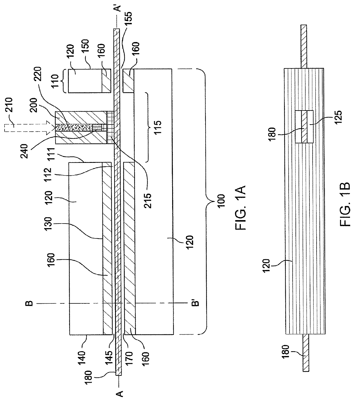
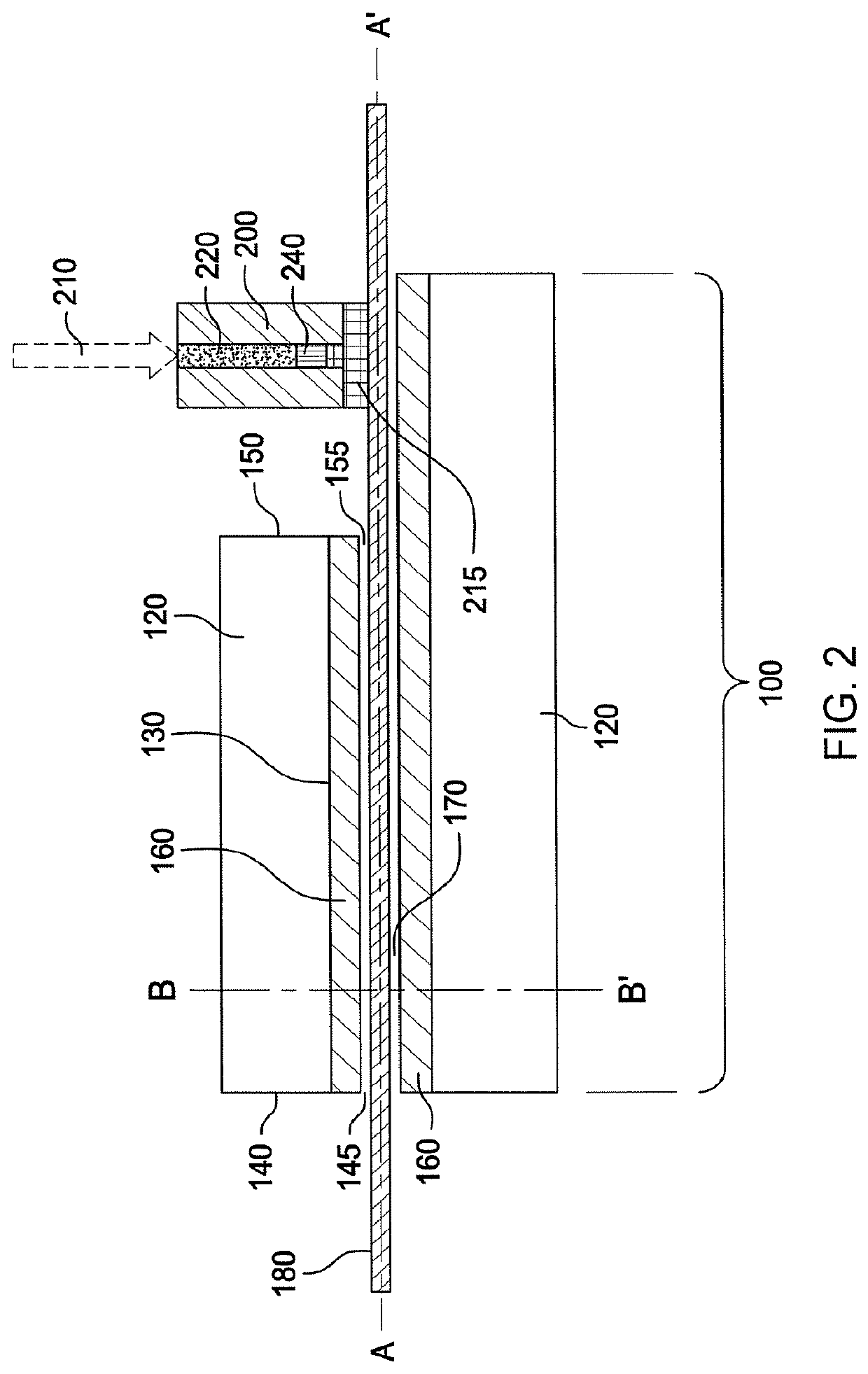
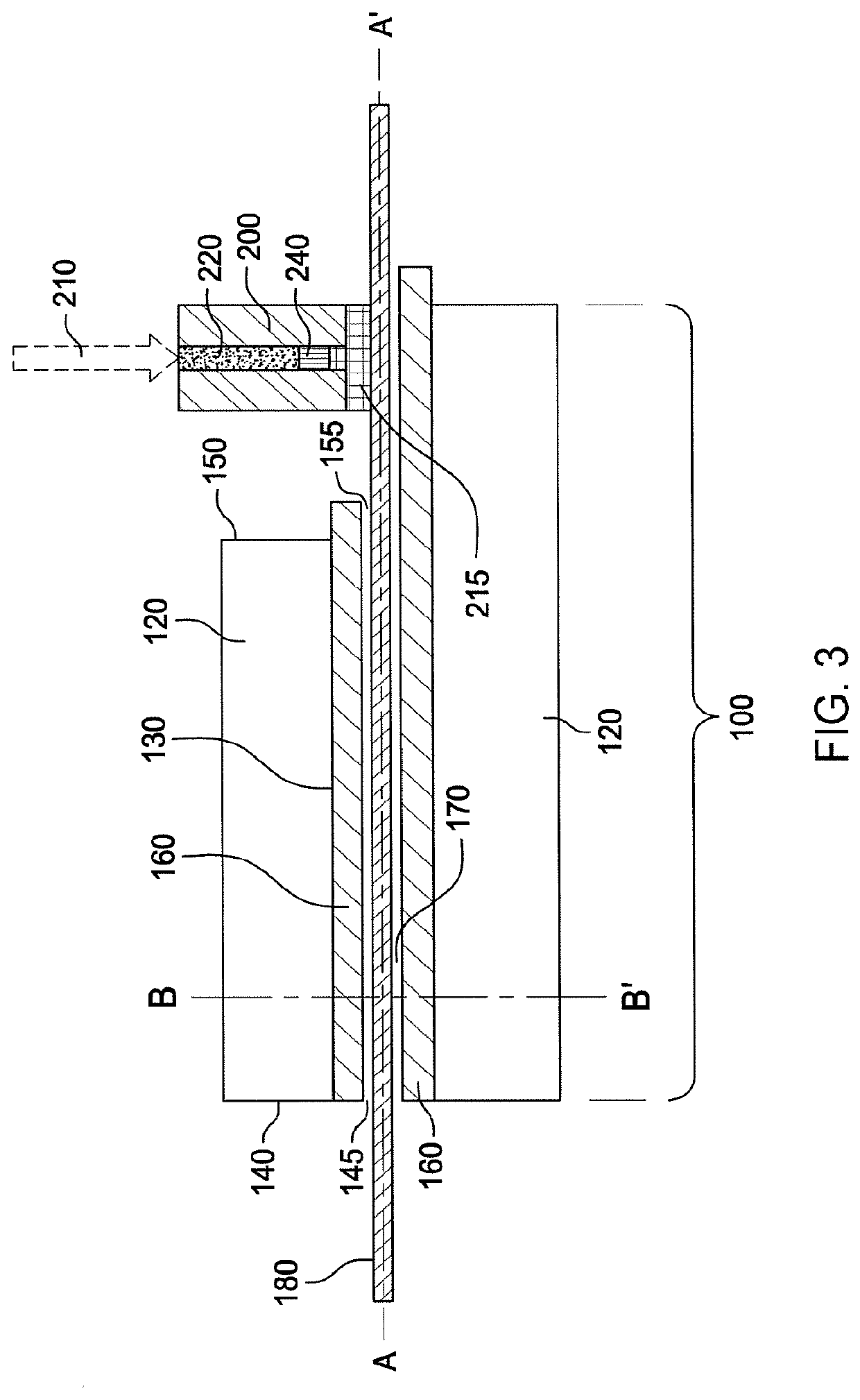
[0084]The first example embodiment of the contact tip assembly is shown schematically in FIGS. 1A and 1B. As illustrated in the figure, the contact tip assembly includes a guide 120 having a longitudinal center axis A-A′, a first end 140, and an opposite second end 150, and a linear center bore 130 extending and running along the longitudinal center axis of the guide 120 from its first end 140 to its second end 150. Also present is an electrically insulating lining 160 inside of the center bore 130, the electrically insulating lining 160 extending at least from the first end 140 to the second end 150 of the guide 120. The electrically insulating lining 160 includes a guide channel 170 having an inlet opening 145 at the first end 140 and an outlet opening 155 at the second end 150 and running through the linear electrically insulating lining 160 along the longitudinal center axis A-A′. The electrically insulating lining 160 guides a metal wire 180 being passed through the linear cyli...

second example embodiment

[0089]The second example embodiment of the contact tip assembly is shown schematically in FIGS. 4A and 4B. As illustrated in the figure, the contact tip assembly includes a guide 120 having a longitudinal center axis A-A′, a first end 140, and an opposite second end 150, and a linear center bore 130 extending and running along the longitudinal center axis of the guide 120 from its first end 140 to its second end 150. Also present is an electrically insulating lining 160 inside of the center bore 130, the electrically insulating lining 160 extending at least from the first end 140 to the second end 150 of the guide 120. The electrically insulating lining 160 includes a guide channel 170 having an inlet opening 145 at the first end 140 and an outlet opening 155 at the second end 150 and running through the linear electrically insulating lining 160 along the longitudinal center axis A-A′. The electrically insulating lining 160 guides a metal wire 180 being passed through the linear cyl...


PUM

PropertyMeasurementUnit
voltageaaaaaaaaaa
Currentaaaaaaaaaa
diameteraaaaaaaaaa

Abstract

A contact tip assembly having an electric contact unit containing a contact tip with an electric energy source, where the electric contact unit is positioned at a distance away from the outlet opening of a guide.

Description

RELATED APPLICATIONS[0001]This application is a continuation of U.S. patent application Ser. No. 15 / 206,149, titled “CONTACT TIP CONTACT ARRANGEMENT FOR METAL WELDING”, filed Jul. 8, 2016, the subject matter of which is incorporated herein by reference in its entirety.FIELD OF THE INVENTION[0002]The present invention relates to a contact tip suited for electrically connecting and guiding a welding wire in metal inert gas welding (MIG-welding).BACKGROUND OF THE INVENTION[0003]Structured metal parts made of titanium or titanium alloys are conventionally made by casting, forging or machining from a billet. These techniques have a disadvantage of high material use of the expensive titanium metal and large lead times in the fabrication.[0004]Fully dense physical objects may be made by a manufacturing technology known as rapid prototyping, rapid manufacturing, layered manufacturing, solid freeform manufacturing, additive fabrication, additive manufacturing or 3D printing. This technique e...

Claims


Application Information

Patent Timeline
Patent Type & Authority Applications(United States)
IPC IPC(8): B23K9/04B23K9/29B23K9/12G05B19/4099B23K9/26B23K9/095B23K9/173
CPCB23K9/044B23K9/295B23K9/123G05B19/4099B33Y10/00B23K9/26B23K9/042B23K9/0953B23K9/1735B23K9/122B33Y30/00Y02P10/25
Inventor STRUKSNES, KNUTFORSETH, TRONDRAMSLAND, ARNEKRISTIANSEN, ANDRE
Owner NORSK TITANIUM
Why Eureka
Try Eureka