Hyperspectral quantitative imaging cytometry system

Pending Publication Date: 2022-07-21
CYTOGNOS
View PDF0 Cites 0 Cited by
  • Summary
  • Abstract
  • Description
  • Claims
  • Application Information

AI Technical Summary

Benefits of technology

The patent text is saying that background correction helps to show small changes in signal intensity.

Problems solved by technology

Each of those cells present a specific phenotype resulting from its interaction with the histological environment and any deregulation of these mechanisms may result in diseases like cancer.
In both cases a correct identification of the lineage and functional status of those cells is mandatory and, particularly in the case of small lymphocytes, even the morphological evaluation from an expert is not enough to unravel the nature, origin and heterogeneity of those cells.
However, these technologies cannot work with tissue specimens without disturbing their native architecture and are not capable of studying constituents of the extracellular environment of the tissue.
On the other hand, despite being the standard choice for cellular morphology visualization and spatial localization, microscopy instruments fail to allow a quantitative and objective analysis of cellular components on statistically significant number of cells and lack the standardization capabilities existent in other methodologies like flow cytometry.
Nevertheless, both approaches are considerably slow due to the need for studying the biological tissue one pixel at a time.
This approach maintains the architectural structure of the samples (usually biological solid tissues) but is not quantitative and lacks the multiparametric dimension needed for complex studies.
For this reason, and despite being a snap-shot system, where all the “colors” are sampled simultaneously, it is a very slow methodology.
Moreover, this technology remained limited to a very limited potential in terms of multiplexing, only allowing the study of 3-4 simultaneous parameters.
Nevertheless, since, like in LSC, the sample is “imaged” in a single pixel basis, it suffers from the same drawbacks being a very slow technology.

Method used


Image

  • Hyperspectral quantitative imaging cytometry system
  • Hyperspectral quantitative imaging cytometry system
  • Hyperspectral quantitative imaging cytometry system

Examples


Embodiment Construction

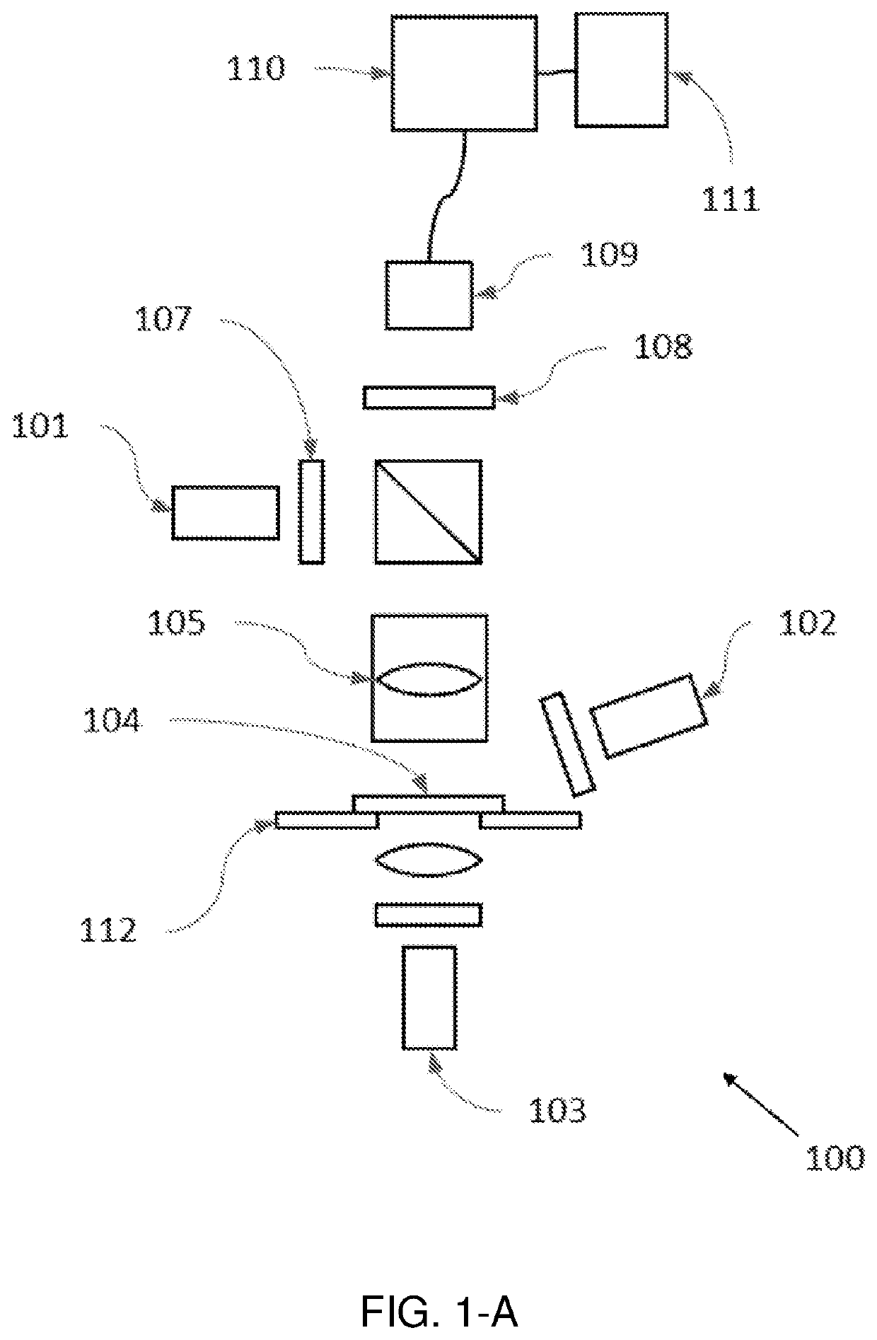
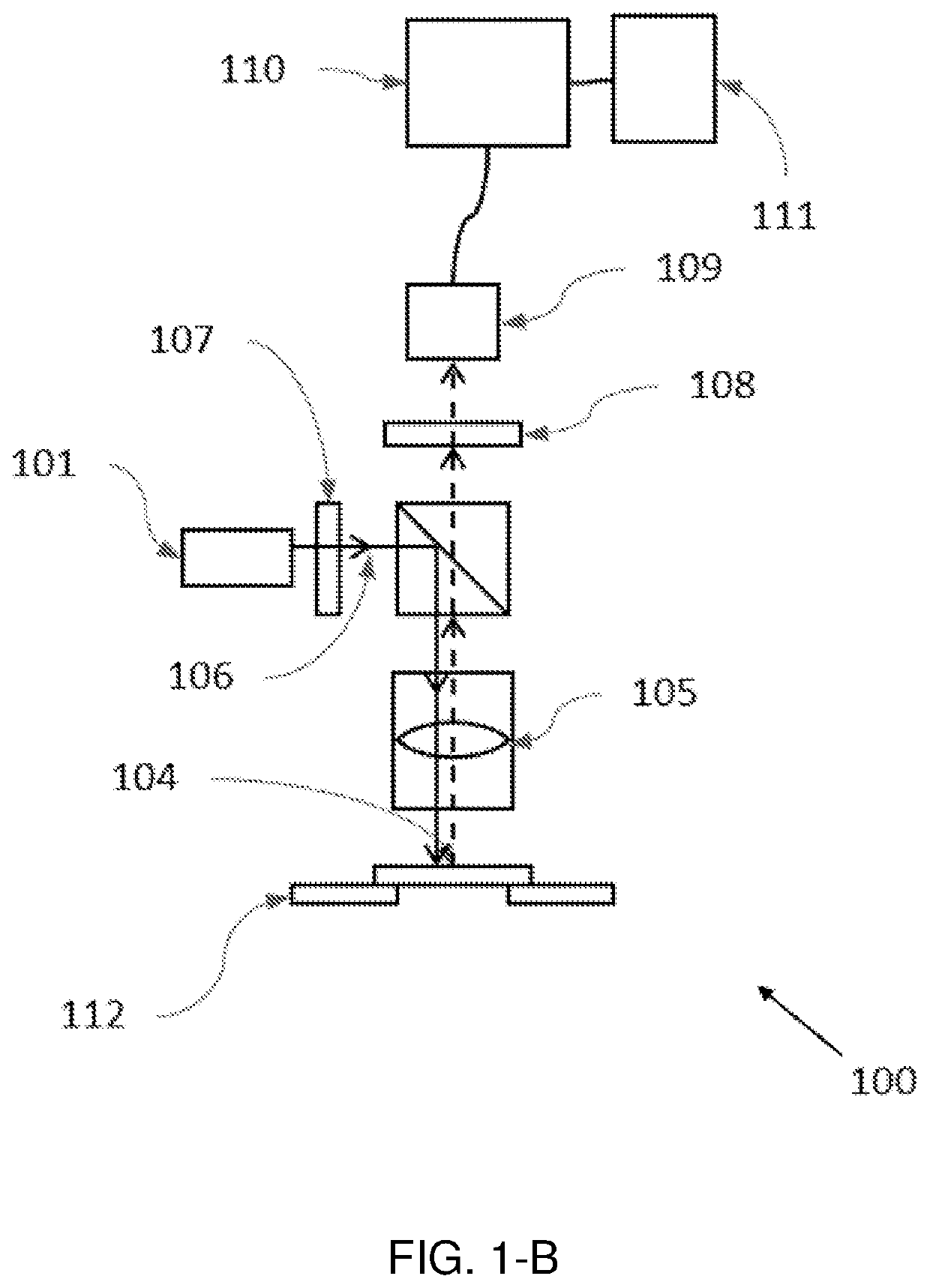
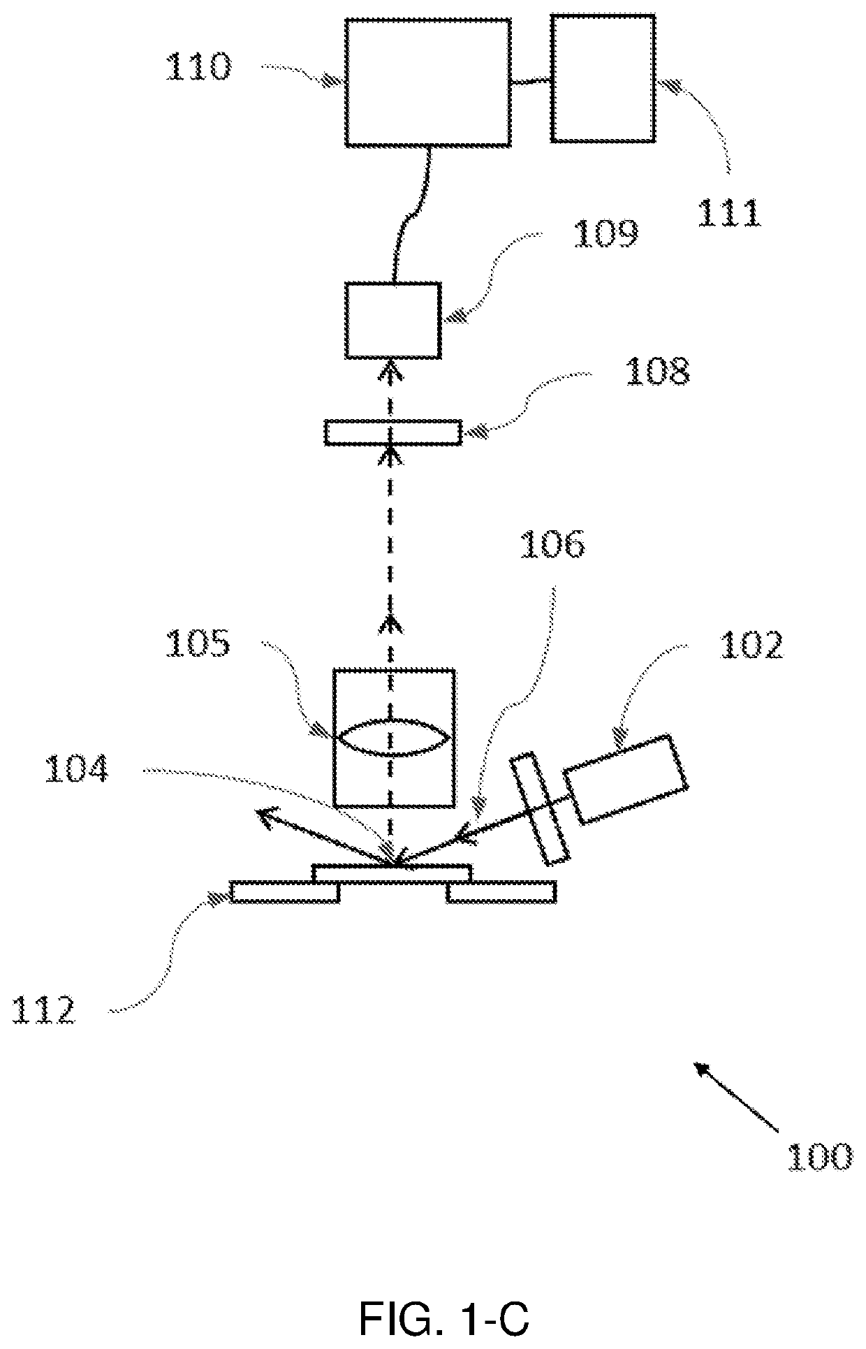
[0103]A hyperspectral quantitative imaging cytometry system (100) according to the invention is schematically shown in FIGS. 1-A to 1-E.

[0104]The system (100) comprises an observation region (104), comprising a sample holder (112) configured to hold one or more solid-phase samples. In an embodiment the sample holder is configured to retain at least one solid phase sample support, each support being adapted to contain an immobilized sample, preferably a biological sample. These solid phase sample supports may be of different materials, preferably crystalline and transparent to light (e.g. glass or plastic), and may have different shapes and sizes, such as rectangular shape (e.g. a microscope slide).

[0105]The biological samples may be of human, animal, fungal or plant origin and may be used alone or in combination with a molecular tag.

[0106]Preferably, a molecular tag is used to reveal the components of the biological sample. The reporter part of the molecular tag may luminesce or sel...


PUM


Abstract

A hyperspectral detection system of luminescence from solid phase samples that are stimulated with radiation sources. includes an observation region, a sample holder configured to hold one or more solid-phase samples, at least one radiation source configured to irradiate the observation region, and a collector configured to collect the radiation emitted through or reflected by the sample upon irradiation by the at least one radiation source. The collector has a magnification factor value (M) equal to or lower than 20, and has a numerical aperture value equal to or higher than 0.25. A multichannel filter is configured to selectively filter the wavelength of the radiation collected by the collector, and an image sensor is configured to receive the filtered radiation and generate an image that is a two-dimensional map of the sample.

Description

TECHNICAL FIELD OF THE INVENTION[0001]The present invention relates to hyperspectral detection of luminescence and, in particular, to the detection of luminescence from solid phase samples which are stimulated with radiation sources.BACKGROUND OF THE INVENTION[0002]The function of a biological tissue is the result of the coordinated action of its cellular components. Each of those cells present a specific phenotype resulting from its interaction with the histological environment and any deregulation of these mechanisms may result in diseases like cancer. Therefore, being able to analyze single-cell characteristics within a spatial context is essential to understand how tissues work under normal and disease situations and to help the development of effective treatments.[0003]The result of a disease affecting a specific tissue may not always be noticeable by classical histological and morphological evaluation. Some structures and components of the tissues may appear morphologically si...

Claims


Application Information

Patent Timeline
IPC IPC(8): G01N15/14G01J3/32
CPCG01N15/1463G01J2003/1243G01N15/1429G01J3/32G01N2015/144G01J2003/2826G01N2015/1006G01J3/26G01J2003/1234G01J2003/123G01J2003/102G01J3/2823G01N15/1433
Inventor TENERA MORGADO, JOSÉ MÁRIORODRÍGUEZ DE LA GALA, ÁLVARO
Owner CYTOGNOS
Why Eureka
Try Eureka