Thrombus treatment platform

a technology for thrombolysis and treatment platforms, applied in the field of thrombolysis treatment platforms, can solve the problems of high risk of bleeding in catheter-directed thrombolysis, high surgical risk, and many patients' inability to benefit from treatmen

Pending Publication Date: 2022-08-11
SUZHOU VENMED TECH CO LTD
View PDF0 Cites 3 Cited by
  • Summary
  • Abstract
  • Description
  • Claims
  • Application Information

AI Technical Summary

Benefits of technology

[0006]The technical problem to be solved by the present disclosure is to provide a thrombus treatment platform that can reduce the occurrence of sequelae of thrombus removal.
[0016]When the present disclosure is in use, by arranging the filter assembly downstream of the blood flow, thrombus can be prevented from flowing into other sites along the blood flow; and by inletting thrombolytic drugs, and dragging the stirring device back and forth to make the stirrer move back and forth in the blood vessel, the stirrer scrapes the blood vessel wall back and forth and stirs the thrombus in the blood vessel, or through a driving device, the stirrer is driven to rotate to break the thrombus, or through ultrasonic turbulence, the thrombus falling off from the blood vessel wall, the thrombus breaking and the thrombus. capturing are achieved; and with the aspiration catheter to aspirate thrombus, a large number of deep vein thrombus and old thrombus can be quickly removed without damaging the blood vessel wall and venous valve, reducing the sequelae of thrombus removal.
[0017]The aspiration catheter of the present disclosure can also provide access to other thrombus removal devices on the premise that it has the function of thrombus removal, thereby facilitating doctors to select surgical schemes for different thrombus, thereby making this thrombus treatment platform applicable to a wide range of indications.
[0021]Due to the implementation of the above technical solutions, the present disclosure has the following advantages over the prior art:
[0022]The present disclosure can remove thrombus under the condition of ensuring relative safety, and is particularly suitable for removing a large number of thrombus in the inferior vena cava, protects venous valves and venous vessel walls, has controllable blood loss and simple operation steps, shortens operation time, and reduces patient hospitalization expenses.

Problems solved by technology

Catheter-directed thrombolysis has a high risk of bleeding due to thrombolytic drugs, and its surgical indications are extremely strict.
Many patients have contraindications to catheter-directed thrombolysis, so many patients cannot benefit from it.
However, the above-mentioned thrombus removal device is complicated in structure, high in preparation cost, and cumbersome to use, and when the thrombus on the blood vessel wall is peeled off by the rotation of the spiral cutter or the spiral rotating piece in the blood vessel, it is easy to damage the blood vessel endothelium, which may easily lead to the occurrence of sequelae of thrombus removal.
However, too long a negative pressure time often causes the patient to lose too much blood, and at the same time, high-pressure rapid stirring may cause red blood cell damage and hemolysis which may easily lead to sequelae of thrombus removal.

Method used


Image

  • Thrombus treatment platform
  • Thrombus treatment platform
  • Thrombus treatment platform

Examples


embodiment 1

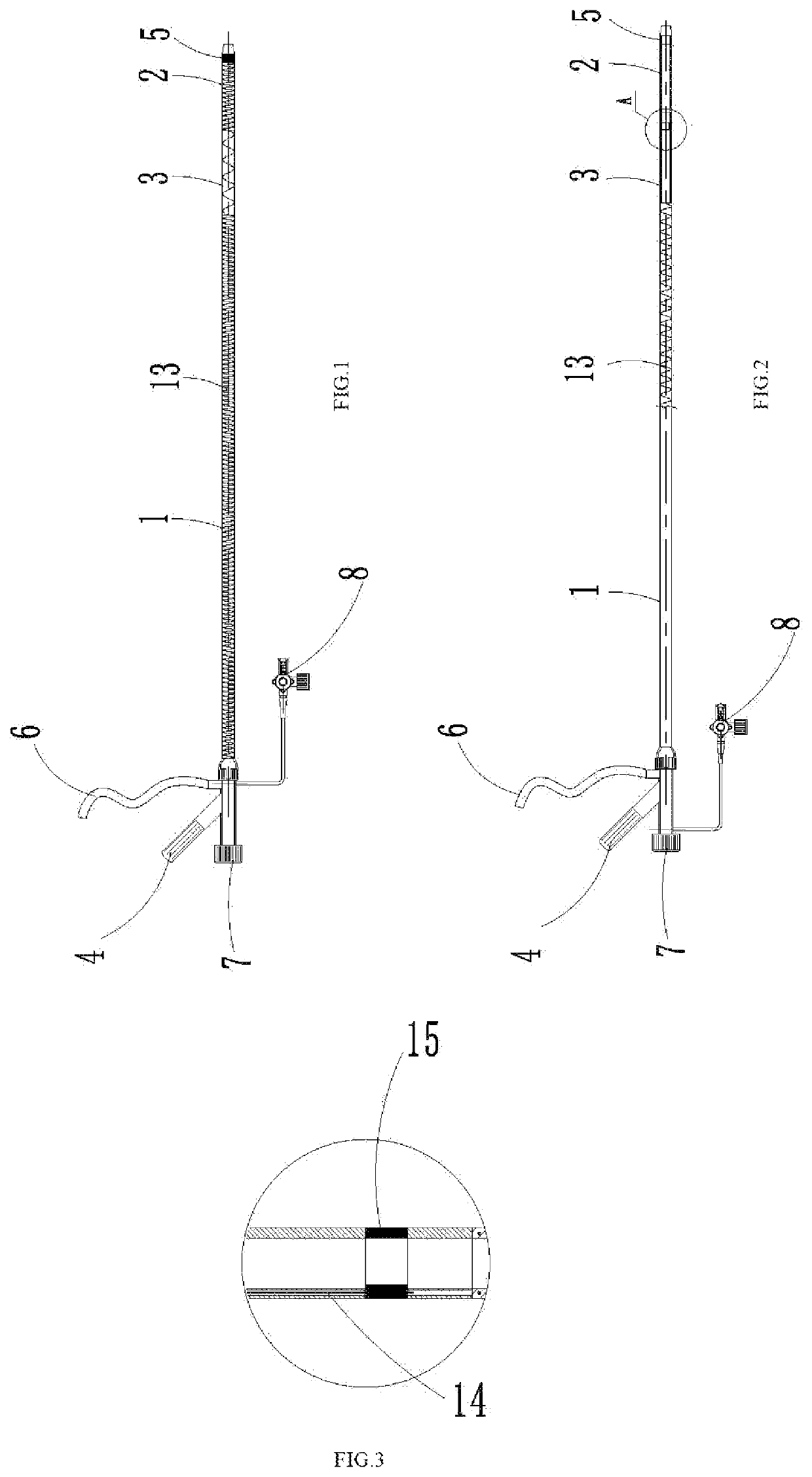
[0089]FIGS. 1 to 4 show Embodiment 1, where the connecting piece 14 is only one steel wire, and the distal end of the connecting piece 14 is fixedly connected to the developing ring, and the proximal end is wound around the operating portion 4, at this time, there is only one connection point between the connecting piece 14 and the developing ring, therefore, when the operating portion 4 is rotated, the catheter part can only be bent in a single direction, and the angle range that can be bent is 0 to 90°, the angle range shown in FIG. 4 is 0° and 30°.

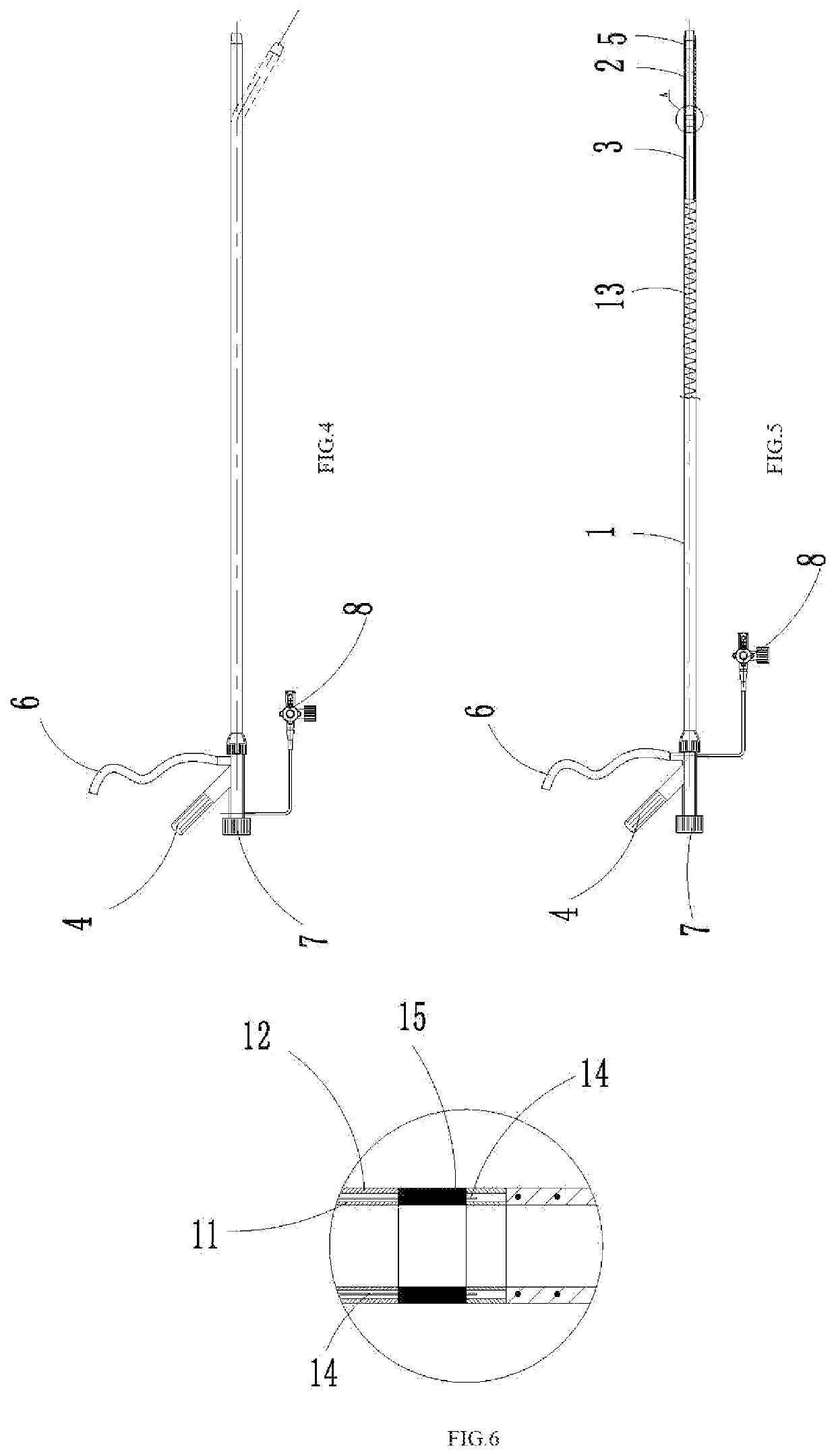
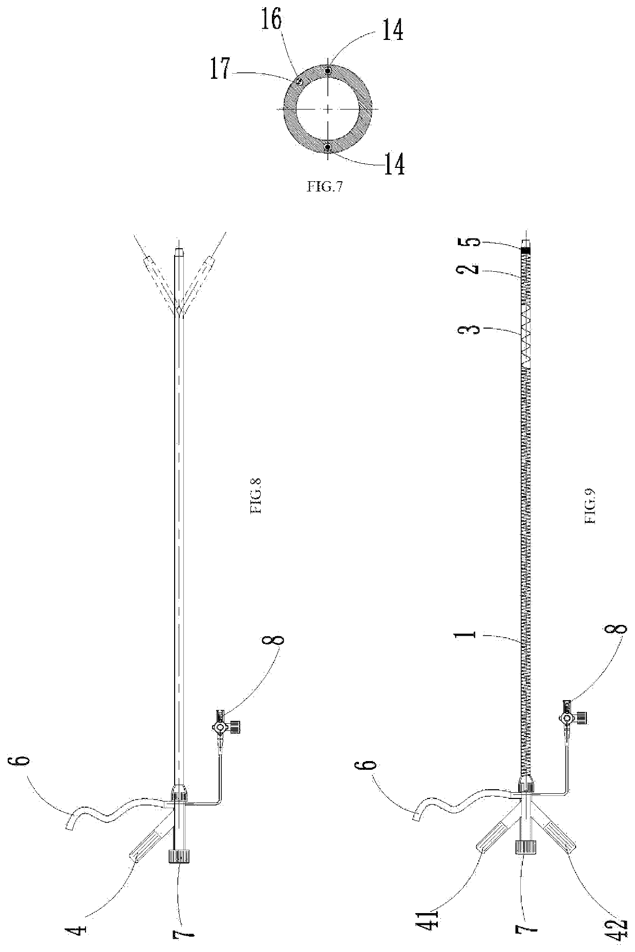
[0090]FIGS. 1, 5 to 8 show Embodiment 2, where the connecting piece 14 is also one steel wire, but the two end portions of the connecting piece 14 (that is, the distal ends of the connecting piece 14) are respectively fixedly connected to opposite sides of the fixing piece 15, and the middle position of the connecting piece 14 is wound on the operating portion 4, so that the connecting piece 14 is divided into two parts by the operating...

embodiment 5

[0125]The structure of the operating device in this embodiment is basically the same as the operating device used in the stirrer of Embodiment 5, except for the connection between the first power line 82 and the first ultrasonic connectors 84.

[0126]Under this scheme, as shown in FIGS. 47 to 49, the first power line 82 is located in the inner cavity of the wires 56 and the inner cavity (i.e., the wall) of the second catheter 52; the stirring device further comprises a conductive ring 91 fixed arranged at the proximal end of the first power line 82; the conductive ring 91 is fixedly connected to the second catheter 52, and is slidably sleeved on the first catheter 51 and in contact with the first catheter 51; the first catheter 51 comprises a flexible tube section, a metal tube with the distal end fixedly connected to the proximal end of the flexible tube section, an insulating layer sleeved on the part of the metal tube, the material of the metal tube is stainless steel, etc.; the ma...


PUM


Abstract

A thrombus treatment platform comprises an aspiration catheter, an aspiration pump, a stirring device and a filter assembly, the filter assembly comprises a filter rod and a filter screen; the stirring device comprises a first catheter, a second catheter, a stirrer and an operating device capable of causing the first catheter and the second catheter to slide relatively so that the stirrer can be switched between the expanded state and the collapsed state; the thrombus treatment platform further comprises a driving device capable of driving the rotation of the stirrer. The present disclosure can remove thrombus under the condition of ensuring relative safety, and is particularly suitable for removing a large number of thrombus in the inferior vena cava, protects venous valves and venous vessel walls, has controllable blood loss and simple operation steps, shortens operation time, and reduces patient hospitalization expenses.

Description

TECHNICAL FIELD OF THE INVENTION[0001]The present disclosure belongs to the field of medical apparatus and instruments, specifically relates to a thrombus treatment platform.BACKGROUND OF THE INVENTION[0002]Thrombotic diseases include arterial thrombosis, venous thrombosis, and thromboembolism. The existing treatment methods mainly include vascular incision and thrombectomy, catheter-directed thrombolysis, and percutaneous mechanical thrombectomy. Incision and thronibectomy requires anatomical separation and incision of blood vessels, such as femoral artery incision, femoral vein incision or brachial artery incision, etc.. With the development of endovascular interventional technology and material innovation, this open surgical method is gradually replaced by minimally invasive interventional endovascular therapy, that is, catheter-directed thrombolysis and percutaneous mechanical thrombectomy. Catheter-directed thrombolysis has a high risk of bleeding due to thrombolytic drugs, and...

Claims


Application Information

Patent Timeline
Patent Type & Authority Applications(United States)
IPC IPC(8): A61B17/3207
CPCA61B17/320758A61B2017/22079A61B17/320725A61B17/22A61B2017/22081A61B2017/22084A61B2017/22094A61B17/221A61B2217/005A61B2017/2212A61F2/013A61B17/22012A61B17/2202A61B2017/22074A61B2017/22078
Inventor WANG, XIAOTIANZHANG, LEIFENG, HAIQUANLI, XIAOQIANGWANG, YONGGANGGUAN, LIJUANLI, JING
Owner SUZHOU VENMED TECH CO LTD
Why Eureka
Try Eureka