Ultrasonic doppler blood flow imaging method and system

US20220257218A1Pending Publication Date: 2022-08-18YUNNAN UNIV

Image

  • Ultrasonic doppler blood flow imaging method and system
  • Ultrasonic doppler blood flow imaging method and system
  • Ultrasonic doppler blood flow imaging method and system

Examples


Embodiment Construction

[0060]The technical solutions of the embodiments of the present disclosure are clearly and completely described below in combination with the accompanying drawings. Apparently, the described embodiments are merely a part rather than all of the embodiments of the present disclosure. All other examples obtained by a person of ordinary skill in the art based on the examples of the present disclosure without creative efforts shall fall within the protection scope of the present disclosure.

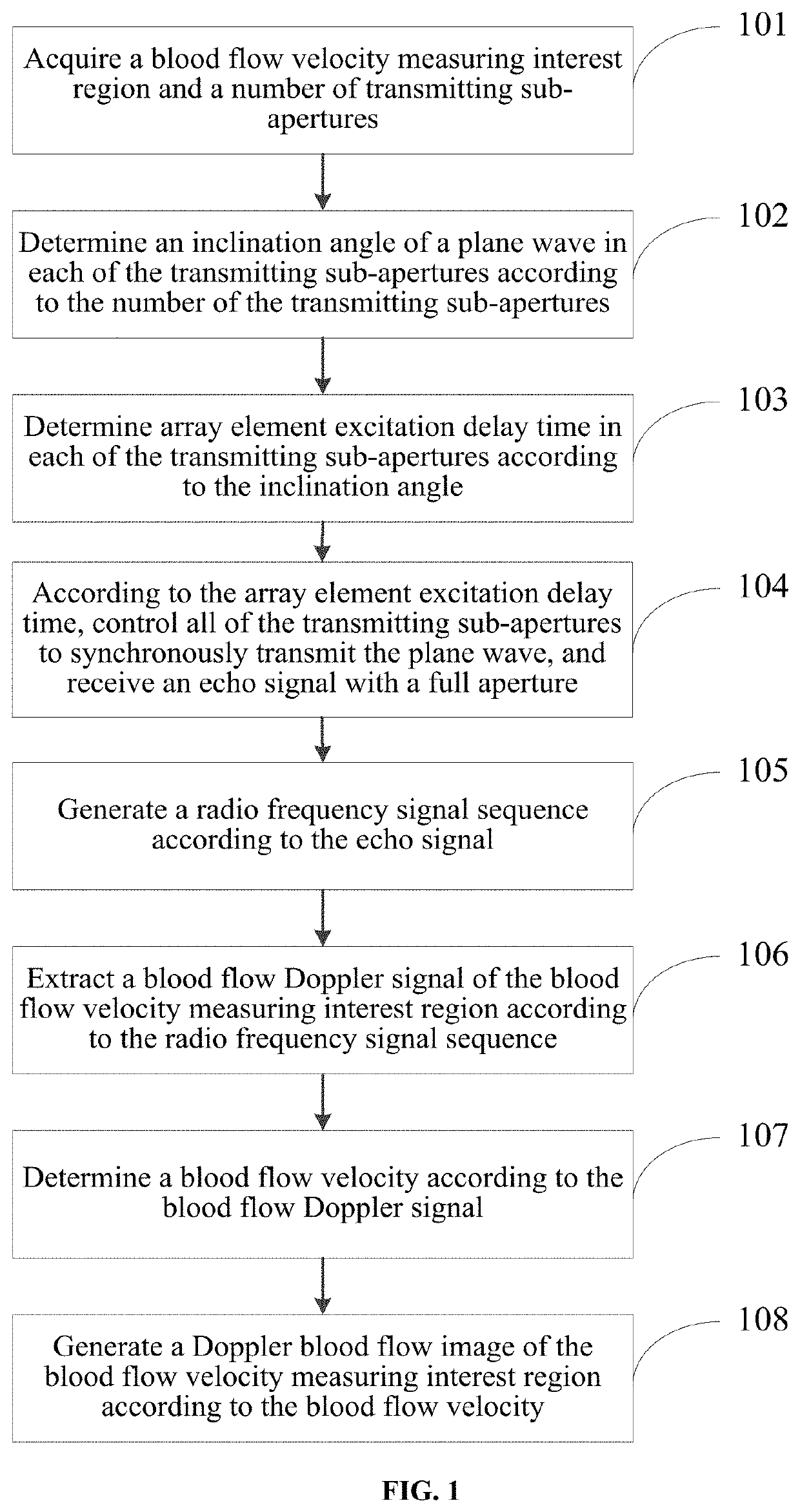
[0061]An objective of the present disclosure is to provide an ultrasonic Doppler blood flow imaging method and system, to maximize the pulse repetition frequency, and suppress the motion artifacts in the compounded radio frequency signal during ultrafast ultrasonic Doppler blood flow imaging.

[0062]To make the above-mentioned objectives, features, and advantages of the present disclosure clearer and more comprehensible, the present disclosure will be further described in detail below in combination with...


PUM


Abstract

An ultrasonic Doppler blood flow imaging method and system are provided. The method includes: acquiring a blood flow velocity measuring interest region and a number of transmitting sub-apertures; determining, according to the number of transmitting sub-apertures, inclination angle of a plane wave in each of the transmitting sub-aperture; determining, according to inclination angle, array element excitation delay time in each of the transmitting sub-aperture; controlling, according to array element excitation delay time, all of transmitting sub-apertures to synchronously transmit plane waves, and receiving echo signals with a full aperture; generating a radio frequency signal sequence according to echo signals; extracting blood flow Doppler signals of blood flow velocity measuring interest region according to radio frequency signal sequence; determining a blood flow velocity according to blood flow Doppler signals; and generating a Doppler blood flow image of blood flow velocity measuring interest region according to blood flow velocity.

Description

CROSS REFERENCE TO RELATED APPLICATION[0001]The present application claims priority to the Chinese Patent Application No. 202010162200.2, filed with the China National Intellectual Property Administration (CNIPA) on Mar. 10, 2020, and entitled “ULTRASONIC DOPPLER BLOOD FLOW IMAGING METHOD AND SYSTEM”, which is incorporated herein by reference in its entirety.TECHNICAL FIELD[0002]The present disclosure relates to the technical field of ultrasonic Doppler blood flow imaging, and in particular, to an ultrasonic Doppler imaging blood flow method and system.BACKGROUND ART[0003]With the rapid development of modern society, smoking, dyslipidemia, obesity, unhealthy diet and lack of physical exercise and other common bad habits lead to frequent occurrence of atherosclerosis. Meanwhile, the incidence of atherosclerosis-induced vascular diseases is also increasing year after year. Cardio-cerebrovascular diseases, represented by myocardial infarction (MI) and cerebral ischemic stroke, can lead...

Claims


Application Information

Patent Timeline
18 Aug 2022
Publication
US20220257218A1
IPC
A61B8/08; A61B8/06
CPC
A61B8/5276; A61B8/5223; A61B8/488; A61B8/06; A61B8/54
Inventors
ZHANG, YUFENG; HE, BINGBING