
Capsule device having improved self-righting ability

a self-righting ability and capsule technology, applied in the field of capsule devices having improved self-righting ability, can solve the problems of limiting the window of opportunity for drug release, difficult to realise solutions, and insufficient capsule size in many applications

Pending Publication Date: 2022-08-25
NOVO NORDISK AS
View PDF0 Cites 0 Cited by
  • Summary
  • Abstract
  • Description
  • Claims
  • Application Information

AI Technical Summary

Benefits of technology

The invention is about improving the self-righting of a capsule device used in medical applications. The invention provides a low friction surface property on the exterior surface of the capsule device, which allows for slipping movement relative to the tissue of the lumen wall when the capsule device is subjected to gravity torque. This results in better and quicker self-righting of the capsule device, and also allows for improved design-freedom in the capsule device.

Problems solved by technology

To treat their disease these people are required to perform different tasks which may be considered complicated and may be experienced as uncomfortable.
However, such solutions are very difficult to realise, since protein-based drugs will be degraded and digested rather than absorbed when ingested.
This presents several challenges among which are: (1) The drug has to be protected from degradation or digestion by the acid in the stomach.
(2) The drug has to be released while being in the stomach, or in the lower gastrointestinal tract, i.e. after the stomach, which limits the window of opportunity for drug release.
Also, the overall size of the capsule may in many applications be critical.
For example, when aiming for sufficient loading capacity of a capsule having a small size, it may be challenging to obtain a desired centre of mass for the article, and this may result in a reduced ability to self-orient.

Method used


Image

  • Capsule device having improved self-righting ability
  • Capsule device having improved self-righting ability
  • Capsule device having improved self-righting ability

Examples


example 1

Simplified Spherical Device

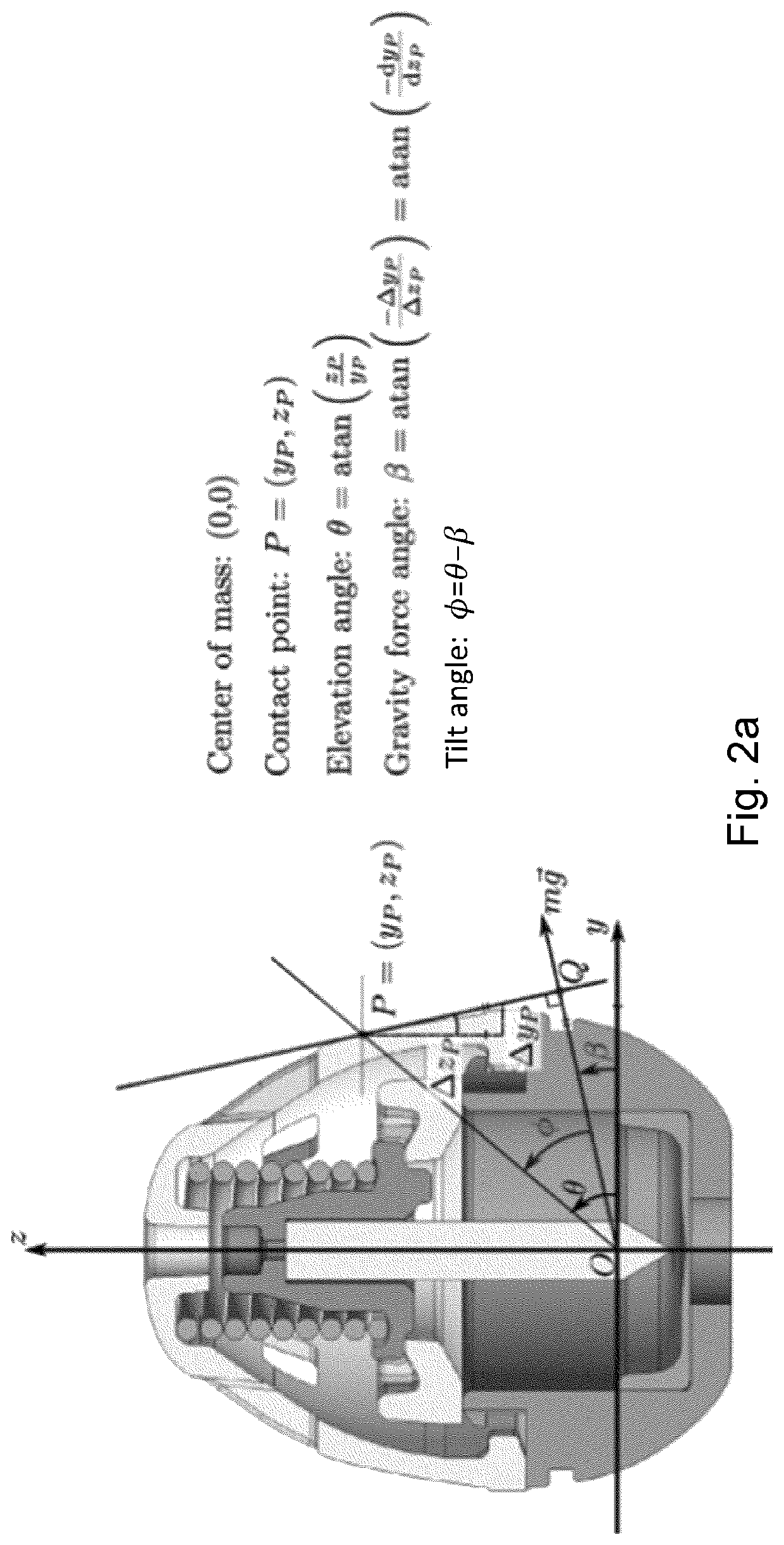
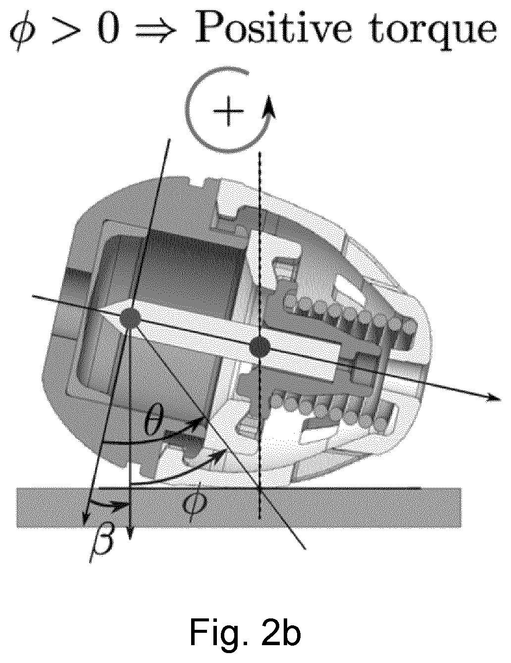
[0124]For this case, the device is considered locally to be spherical with radius R, see FIG. 16.

[0125]Forces[0126]Gravity force: Fgrav=—mg ey [0127]Friction force: Ffric=—,gμex

[0128]Torques (around the center of volume, marked by the black cross)[0129]Gravity torque: τgrav=dgrav Fgrav=1 / 2R cos(α) mg[0130]Friction force: τfric=—dfric Ffric=—R mgμ

[0131]Total torque must be positive to ensure self-righting:

τtot=τgrav+τfric>0⇒μ<h⁢ cos⁡(α)dfric⇒μ<12⁢R⁢ cos⁡(α)R=12⁢cos⁢(α)

[0132]For the center of mass, we observe that many of the proposed self-orienting capsule devices have a center of mass similar (or lower even) to that of 1 / 2R from the center of mass, so here h=1 / 2R, and α=60°, and for the friction force we have dfric=R. The critical coefficient becomes

μc=12⁢R⁢ cos⁡(60⁢°)R=0.25.

[0133]Hence, based on these calculations, in order to ensure that the spherical device according to Example 1 perform slipping movement, the surface properties of the ex...

example 2

Self-Righting Capsule Device, Second Embodiment

[0134]For the second embodiment self-righting capsule device 200 described in connection with FIGS. 6a, 6b and 6c we have the following conditions:[0135]h=3.6 mm, α=42° and dfric=7.3 mm

μ<3.6 mm⁢ cos⁡(42)7.3 mm=0.37⇒μc=0.37

[0136]Hence, based on this design, in order to ensure that the device according to Example 2 perform slipping movement, the surface properties of the exterior surface touching the tissue should have a coefficient of friction below 0.37 and ideally even lower.

example 3

Self-Righting Capsule Device, Third Embodiment

[0137]For the third embodiment self-righting capsule device 300 described in connection with FIGS. 7a, 7b and 7c we have the following conditions:[0138]h=3.4 mm, α=56° and dfric=6.6 mm

μ<3.4 mm⁢ cos⁡(56⁢°)6.6 mm=0.29⇒μc=0.29

[0139]Hence, based on this design, in order to ensure that the device according to Example 3 perform slipping movement, the surface properties of the exterior surface touching the tissue should have a coefficient of friction below 0.29 and ideally even lower.

END OF EXAMPLES

[0140]Turning now to FIGS. 9a and 9b a fourth embodiment of an ingestible self-righting capsule device 400 is shown. Device 400 comprises a first portion 100A having an average density, a second portion 100B having an average density different from the average density of the first portion 100A. The capsule device 400 accommodates a payload portion 130 for carrying an agent for release internally of a subject user that ingests the article. In...


PUM


Abstract

A capsule device suitable for insertion into a lumen of a patient, the lumen having a lumen wall, wherein the capsule device (100, 200, 300, 400, 500) comprises a) a capsule housing (110, 120, 210, 220) having an outside shape formed as a rounded object and defining an exterior surface, and b) a tissue interfacing component (130, 230) disposed relative to the capsule housing (110, 120, 210, 220), the tissue interfacing component (130, 230) configured to interact with the lumen wall at a target location, wherein the capsule device is configured as a self-righting capsule having a geometric center and a center of mass offset from the geometric center along a first axis, wherein when the capsule device (100, 200, 300, 400, 500) is supported by the tissue of the lumen wall while being oriented so that the centre of mass is offset laterally from the geometric center the capsule device experiences an externally applied torque due to gravity acting to orient the capsule device with the first axis oriented along the direction of gravity to enable the tissue interfacing component (130, 230) to interact with the lumen wall at the target location, wherein at least a portion of the exterior surface of the capsule device (100, 200, 300, 400, 500) has a surface property exhibiting one or more surface properties selected from the group consisting of a surface coating, a surface roughness, a surface geometry, and a surface micro-geometry, and wherein said surface property is selected to provide low friction, such as low static friction, ensuring slipping movement of the capsule device relative to the tissue of the lumen wall when said externally applied torque due to gravity acts on the capsule device.

Description

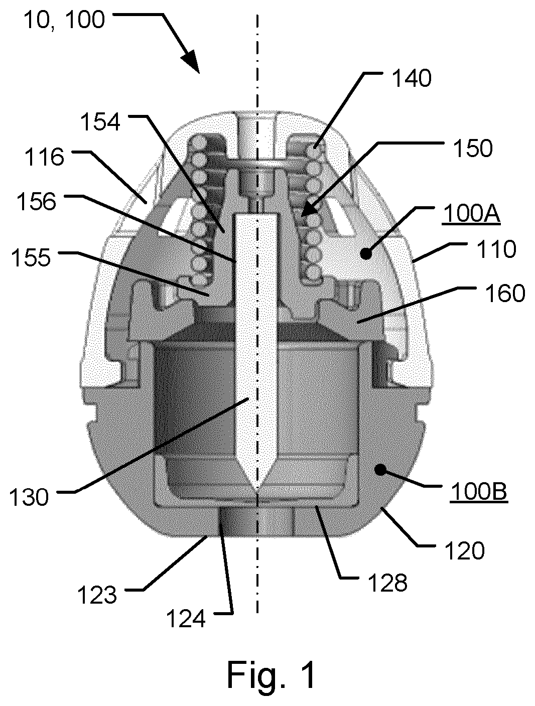
CAPSULE DEVICE HAVING IMPROVED SELF-RIGHTING ABILITY[0001]The present invention relates to capsule devices for medical diagnosis and / or therapy, the capsule devices being adapted for insertion into a lumen of a patient, wherein the capsule devices have an inherent ability to self-orient relative to a supporting surface of a lumen wall.BACKGROUND OF THE INVENTION[0002]In the disclosure of the present invention reference is mostly made to the treatment of a disease by delivery of a drug payload, such as delivery of insulin for treating diabetes. However, this is only an exemplary use of the present invention.[0003]May people suffer from diseases, such as diabetes, which requires them to receive injections of drugs on a regular and often daily basis. To treat their disease these people are required to perform different tasks which may be considered complicated and may be experienced as uncomfortable. Furthermore, it requires them to bring injection devices, needles and drugs with them ...

Claims


Application Information

Patent Timeline
Patent Type & Authority Applications(United States)
IPC IPC(8): A61K9/48A61M31/00A61B5/00A61M5/20
CPCA61K9/4808A61M31/002A61B5/6861A61M5/2033A61M2210/1053A61M2210/005
Inventor HVITFELD LEY, MIKKEL WENNEMOESFREDERIKSEN, MORTEN REVSGAARDJENSEN, BRIAN
Owner NOVO NORDISK AS
Learn More