Target pipeline dynamic thermal failure analysis method in parallel pipeline jet fire scenario

a pipeline and dynamic thermal failure technology, applied in the field of thermal failure prediction and analysis of natural gas transmission pipelines, can solve the problems of increasing spacing, economic cost of construction and maintenance, and it is basically impossible to implement corresponding fire-fighting measures within those hours

Pending Publication Date: 2022-09-08
SOUTH CHINA UNIV OF TECH
View PDF0 Cites 1 Cited by
  • Summary
  • Abstract
  • Description
  • Claims
  • Application Information

AI Technical Summary

Problems solved by technology

In order to meet increasing demand for energy and take actual engineering problems in aspects of limited space conditions of pipeline laying territories, economic cost for construction and maintenance and the like, the situation of laying natural gas transmission pipelines in parallel in a close spacing is increasing.
When the leakage occurs in a source pipeline in the parallel pipeline scenario, a large amount of natural gas stored in the pipe makes jet fires generally last for several hours, moreover, it is basically impossible to implement corresponding fire-fighting measures within those hours.
Rio: Rio Pipeline Conference and Exposition, 2017: 21-30., Ge T M, Hong L, Yao Z. Fire Consequence Analysis for Two Parallel-running Pipelines[C]., ANSYS finite element software, FLUENT software and KFX software are respectively adopted to carry out static thermal response analysis on the target pipeline thermal failure in a jet fire environment; however, none of these methods can calculate failure time; moreover, in these methods, a thermal radiation value received by the target pipeline is set to be a constant value without considering the change process that the thermal radiation value drops along with time in the actual situation.
The document studies showed that the static thermal response analysis and the geometric proportion method adopted in the current studies cannot accurately and objectively reflect the dynamic thermal failure process and the corresponding failure result of the target pipeline in the jet fire environment in the actual situation.
However, these methods and assumptions do not conform to the actual accident scenario situation.

Method used


Image

  • Target pipeline dynamic thermal failure analysis method in parallel pipeline jet fire scenario
  • Target pipeline dynamic thermal failure analysis method in parallel pipeline jet fire scenario
  • Target pipeline dynamic thermal failure analysis method in parallel pipeline jet fire scenario

Examples


Embodiment Construction

[0051]Embodiments of the present invention are further described below with reference to the accompanying drawings, but the embodiments and protection of the present invention are not limited thereto. It needs to be noted that anything not specifically described in detail below can be achieved by those skilled in the art with reference to the prior art.

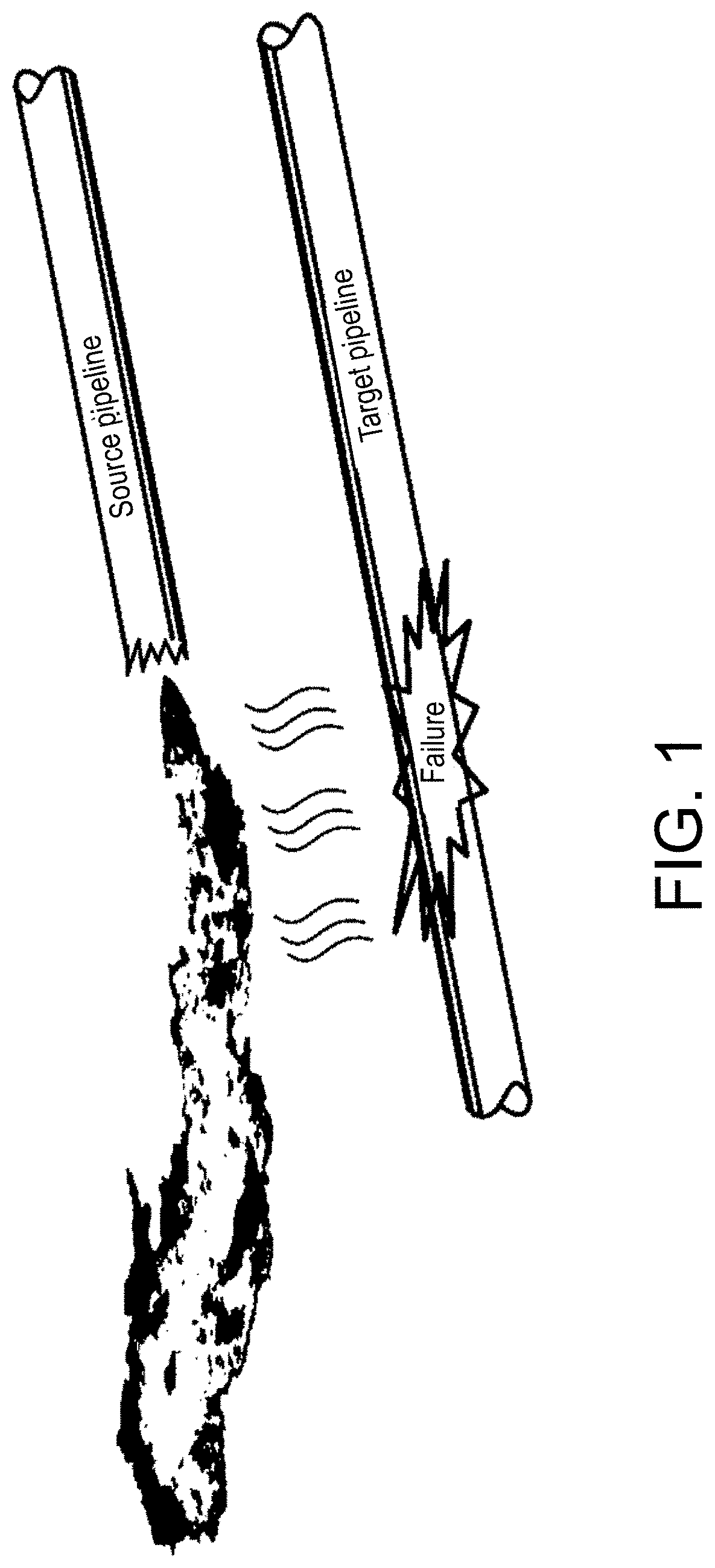
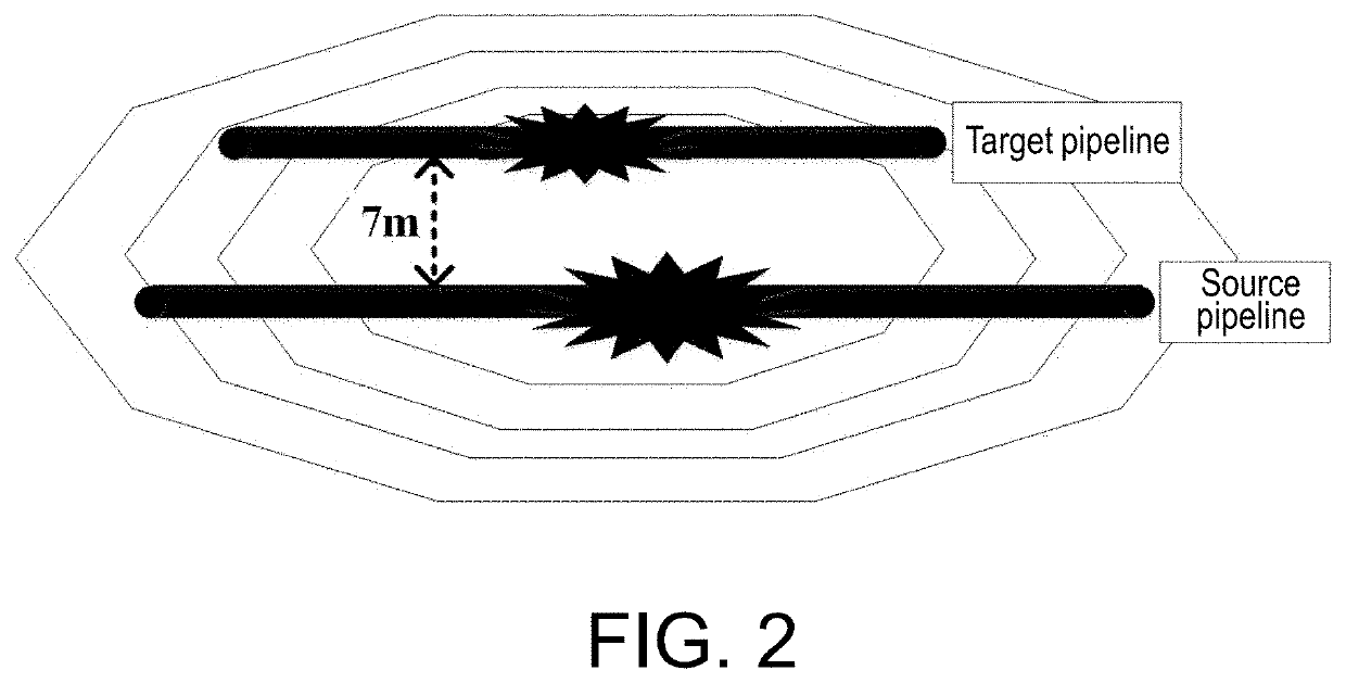
[0052]FIG. 2 is a schematic diagram of a plane of an accident case of parallel natural gas transmission pipelines in accordance with an embodiment. In this typical accident case, a high-pressure natural gas pipeline (a source pipeline) having an outer diameter of 1.067 m bursts first, which produces a crater having a length of 51 m, a width of 23 m, and a depth of 5 m, and makes a part of a pipe section of an adjacent natural gas pipeline (a target pipeline) which is laid in parallel and has an outer diameter of 0.914 m be suspended in the crater. Afterwards, the natural gas is simultaneously ejected from the two ends of the fractured...


PUM


Abstract

Disclosed by the present invention is a target pipeline dynamic thermal failure analysis method in a parallel pipeline jet fire scenario, including the following steps: 1, inputting operation parameters of source pipeline to obtain instantaneous thermal radiation value received by target pipeline in instantaneous jet fire near field; 2, establishing fitting function relational expression of the instantaneous thermal radiation value and time change; 3, calculating instantaneous temperature distribution result of the pipe wall of the target pipeline; 4, calculating convective heat transfer coefficient of inner wall of the target pipeline; 5, calculating instantaneous thermal stress and total instantaneous stress borne by the pipe wall of the target pipeline in a circumferential direction, radial direction and axial direction; 6, carrying out testing to obtain yield strength and ultimate tensile strength corresponding to different temperatures; and 7, analyzing and judging target pipeline dynamic failure result.

Description

CROSS-REFERENCE TO RELATED APPLICATION[0001]This application is a continuation of international application of PCT application serial no. PCT / CN2020 / 142588 filed on Dec. 31, 2020, which claims the priority benefit of China application no. 201911208936.2 filed on Nov. 30, 2019. The entirety of each of the above mentioned patent applications is hereby incorporated by reference herein and made a part of this specification.TECHNICAL FIELD[0002]The present invention relates to the technical field of thermal failure prediction and analysis for natural gas transmission pipelines, and in particular relates to a target pipeline dynamic thermal failure analysis method in a parallel pipeline jet fire scenario.RELATED ART[0003]In order to meet increasing demand for energy and take actual engineering problems in aspects of limited space conditions of pipeline laying territories, economic cost for construction and maintenance and the like, the situation of laying natural gas transmission pipeline...

Claims


Application Information

Patent Timeline
Patent Type & Authority Applications(United States)
IPC IPC(8): A62C35/68G06F30/23
CPCA62C35/68G06F30/23G06F2119/08G06F2113/14G06F2119/02
Inventor CHEN, GUOHUAZHOU, ZHIHANG
Owner SOUTH CHINA UNIV OF TECH
Why Eureka
Try Eureka