
Multi-layer ceramic capacitor

Pending Publication Date: 2022-09-08
TAIYO YUDEN KK
View PDF0 Cites 0 Cited by
  • Summary
  • Abstract
  • Description
  • Claims
  • Application Information

AI Technical Summary

Benefits of technology

The patent describes a way to make a multi-layer ceramic capacitor that can improve its ability to handle voltage and prevent a decrease in its ability to hold an electrostatic charge.

Problems solved by technology

Meanwhile, in the multi-layer ceramic capacitor, in the case where a high voltage is applied to the internal electrodes, the ferroelectricity of the ceramic layer can cause electrolytic strain.
In the case where the side margin is thin, structural defects such as cracks are likely to occur due to stress caused by the electrolytic strain, and it is difficult to achieve sufficient withstand voltage characteristics.

Method used


Image

  • Multi-layer ceramic capacitor
  • Multi-layer ceramic capacitor
  • Multi-layer ceramic capacitor

Examples


first embodiment

I First Embodiment

1. Overall Configuration of Multi-Layer Ceramic Capacitor

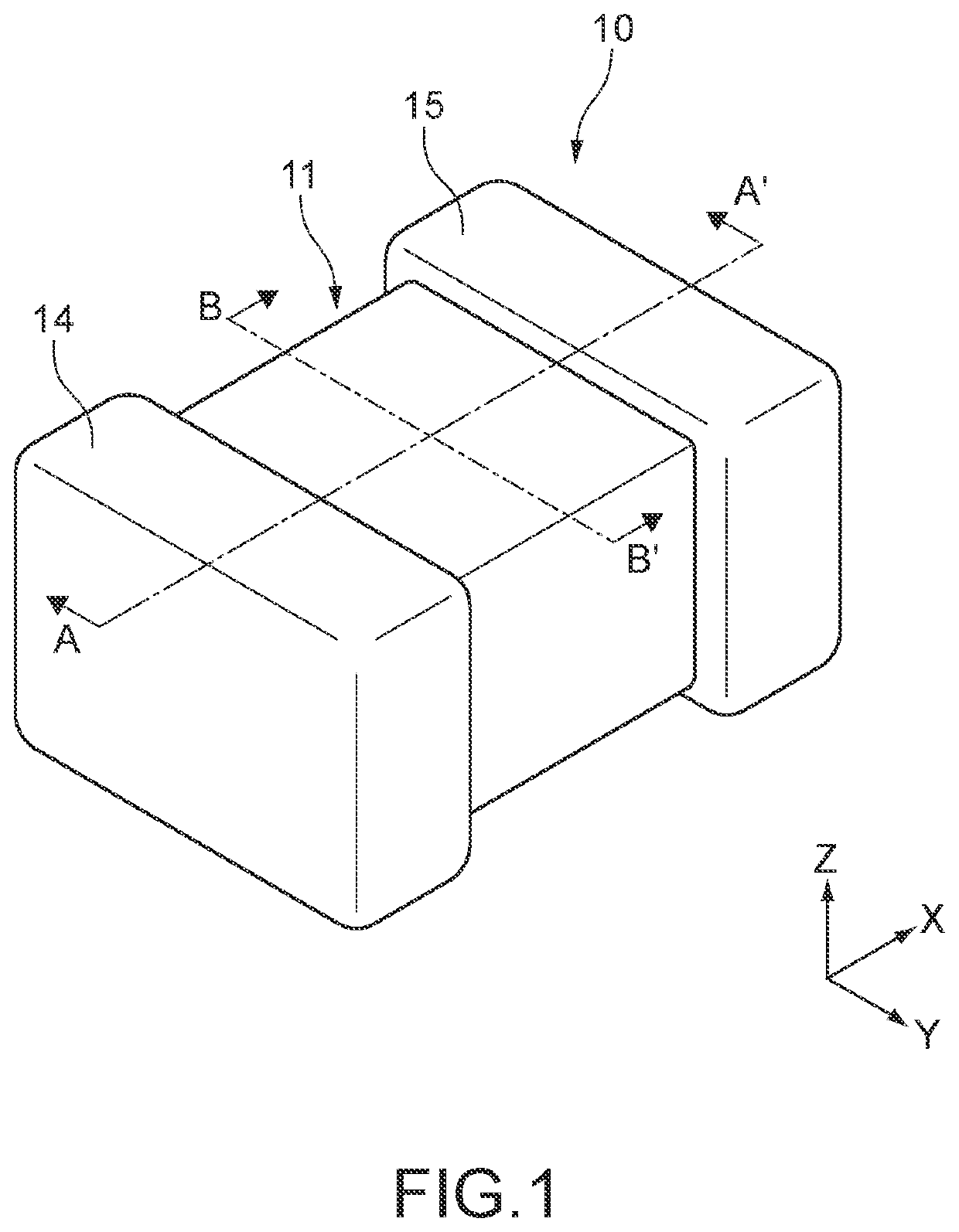
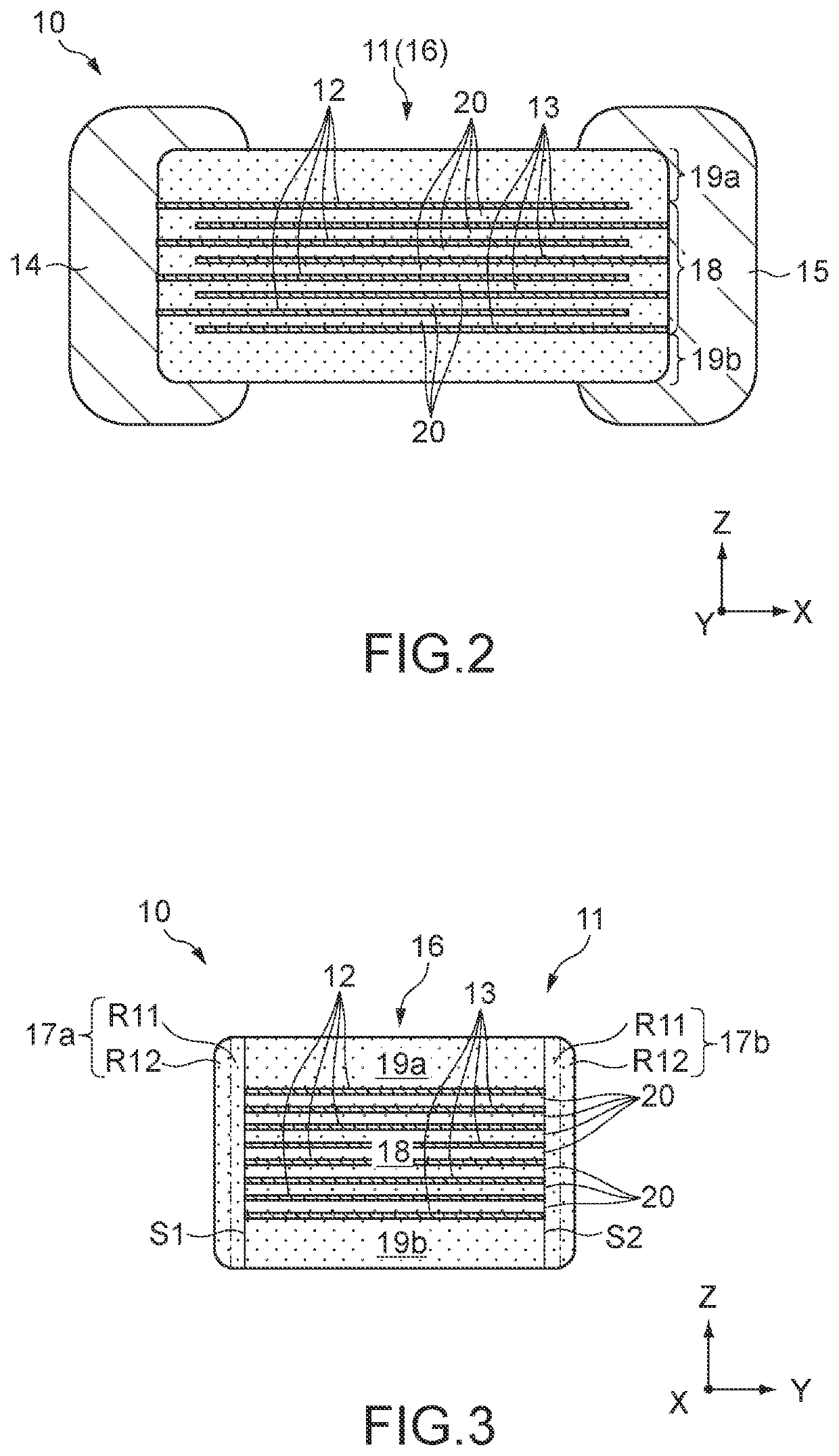
[0043]FIGS. 1 to 3 each show the multi-layer ceramic capacitor 10 according to a first embodiment of the present disclosure. FIG. 1 is a perspective view of the multi-layer ceramic capacitor 10. FIG. 2 is a cross-sectional view of the multi-layer ceramic capacitor 10 taken along the A-A′ line in FIG. 1. FIG. 3 is a cross-sectional view of the multi-layer ceramic capacitor 10 taken along the B-B′ line in FIG. 1.

[0044]The multi-layer ceramic capacitor 10 includes a ceramic body 11, a first external electrode 14, and a second external electrode 15. The ceramic body 11 is formed to have a substantially hexahedron having a first end surface and a second end surface orthogonal to the X-axis direction, a first side surface and a second side surface orthogonal to the Y-axis direction, and a first main surface and a second main surface orthogonal to the Z-axis direction. Ridges connecting the respective surfaces of th...

second embodiment

II Second Embodiment

[0121]Although the first inner region R11 and the first outer region R12 of the first and second side margins 17a and 17b have predetermined element distribution in the first embodiment, also first and second covers 39a and 39b may have similar element distribution.

[0122]Note that in the following embodiment, the same configurations as those in the first embodiment will be denoted by the same reference symbols and description thereof will be omitted.

[0123]FIG. 8 is a cross-sectional view of a multi-layer ceramic capacitor 30 according to a second embodiment of the present disclosure, and shows the cross section of at the same position to that in FIG. 3.

[0124]The multi-layer ceramic capacitor 30 includes a ceramic body 31 different from that in the first embodiment and the first external electrode 14 and the second external electrode 15 similar to those in the first embodiment. Note that in FIG. 8, illustration of the first and second external electrodes 14 and 15...


PUM

PropertyMeasurementUnit
Lengthaaaaaaaaaa
Lengthaaaaaaaaaa
Thicknessaaaaaaaaaa

Abstract

A multi-layer ceramic capacitor includes: a multi-layer unit including ceramic layers laminated in a first direction and electrodes disposed between the ceramic layers, positions of end portions of the electrodes falling within a range of 0.5 μm in a second direction; and side margins each containing manganese or magnesium and silicon and facing each other in the second direction. When each margin is equally divided into an inner region and an outer region, a total concentration of manganese and magnesium in the outer region is higher than a total concentration of manganese and magnesium in the inner region and higher than a total concentration of manganese and magnesium in the ceramic layers, and a concentration of silicon in the inner region is not less than a concentration of silicon in the outer region and higher than a concentration of silicon in the ceramic layers.

Description

CROSS-REFERENCE TO RELATED APPLICATIONS[0001]This application claims the benefit of Japanese Application No. 2021-032288, filed Mar. 2, 2021, in the Japanese Patent Office. All disclosures of the document named above are incorporated herein by reference.BACKGROUND ART[0002]The present disclosure relates to a multi-layer ceramic capacitor including a side margin.[0003]A multi-layer ceramic capacitor in which a side margin has been provided in a later step to a side surface of a multi-layer unit in which ceramic layers and internal electrodes are laminated is known (see, for example, Japanese Patent Application Laid-open No. 2012-209539). This configuration is advantageous for the miniaturization and increase in the capacity of the multi-layer ceramic capacitor because the side surface of the multi-layer unit, from which the internal electrodes are exposed, can be reliably protected even with a thin side margin.[0004]From the viewpoint of extending the crossing area of internal electr...

Claims


Application Information

Patent Timeline
IPC IPC(8): H01G4/30H01G4/12H01G4/012
CPCH01G4/30H01G4/1227H01G4/012H01G4/1209H01G4/002H01G4/1236H01G4/224
Inventor MIZUNO, KOTARO
Owner TAIYO YUDEN KK
Learn More