Parallel branched resonant converter

Active Publication Date: 2022-09-15
EXCELSYS TECH LTD
View PDF29 Cites 0 Cited by
  • Summary
  • Abstract
  • Description
  • Claims
  • Application Information

AI Technical Summary

Benefits of technology

The patent text describes a new design for resonant converters that can improve efficiency and allow for higher power applications. The design involves separating transformers into different groups, each containing multiple transformers connected in parallel. This helps to minimize losses and reduce heat dissipation challenges. The resonant converter has a switch network, a resonant tank, and a rectifier network, and can achieve high efficiency and low component count. Overall, the design provides a more efficient and cost-effective way to drive multiple groups of transformers.

Problems solved by technology

As described above, in some cases, existing LLC resonant converter topologies may not be viable for high power applications due to significant power loss, thermal challenges and multiple high frequency eddy currents.
However, each branch uses a distinct parallel resonant inductor leading to much larger package / board requirements, and greater heat dissipation challenges.

Method used


Image

  • Parallel branched resonant converter
  • Parallel branched resonant converter
  • Parallel branched resonant converter

Examples


Embodiment Construction

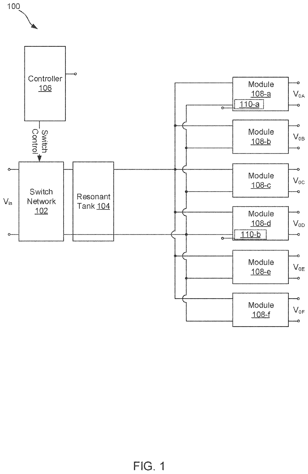
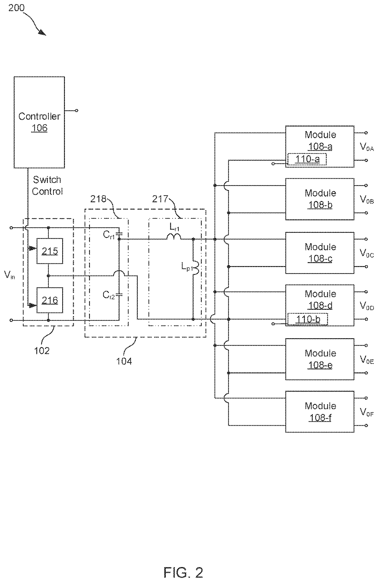
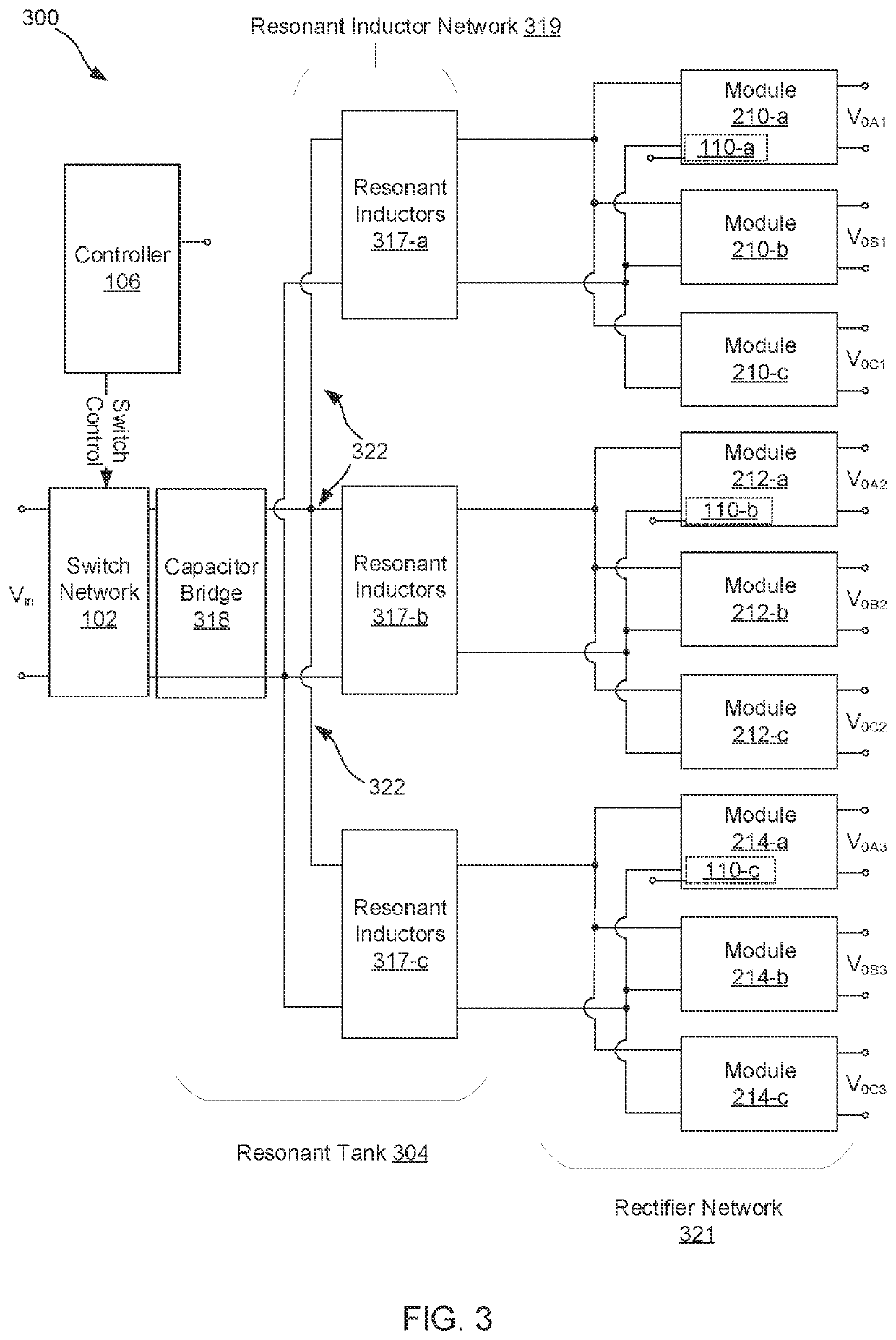
[0036]The present disclosure relates generally to a branched resonant converter configured for driving multiple groups of transformers with the primary windings of the transformers in each group or branch connected in parallel. More specifically, but without limitation, the present disclosure relates to minimizing losses in the series resonant inductors coupled to the primary windings of the transformers by separating the transformers into different groups, each group consisting of a plurality of transformers having their primary windings connected in parallel.

[0037]The word “exemplary” is used herein to mean “serving as an example, instance, or illustration.” Any embodiment described herein as “exemplary” is not necessarily to be construed as preferred or advantageous over other embodiments.

[0038]Preliminary note: the flowcharts and block diagrams in the following Figures illustrate the architecture, functionality, and operation of possible implementations of systems, methods and c...


PUM


Abstract

This disclosure describes systems, methods, and apparatus for driving a plurality of output circuits from a DC input signal using a resonant converter, the resonant converter comprising a switch network, a resonant tank, and a rectifier network, the resonant tank comprising: a resonant capacitor bridge coupled across the switch network; a plurality of branches, each branch comprising at least one series inductor coupled at a first end to the resonant capacitor bridge and at a second end to the rectifier network; and at least one parallel inductor; the rectifier network comprising one or more groups of transformers, each group coupled to one branch of the plurality of branches, and wherein the primary windings of the transformers of each group are coupled in parallel, and wherein the secondary windings are configured for coupling to an output load.

Description

FIELD OF THE DISCLOSURE[0001]The present disclosure relates generally to a resonant converter. In particular, but not by way of limitation, the present disclosure relates to systems, methods and apparatuses for driving multiple transformers using a resonant converter.DESCRIPTION OF RELATED ART[0002]Resonant converters, such as LLC resonant converters, are widely used in commercial applications such as consumer electronics. In a conventional LLC resonant converter circuit, a DC input signal is converted to a square wave signal by an inverter circuit. The square wave signal is further coupled to multiple transformers via a resonant tank. To obtain DC output voltage, the sinusoidal output current isolated from the resonant tank by the transformer is rectified and stabilized by a large capacitance, hence providing a stable output DC voltage at the load.[0003]However, the state of existing LLC resonant converters, especially for high power applications, is challenged due to significant p...

Claims


Application Information

Patent Timeline
IPC IPC(8): H02M3/335H02M3/28
CPCH02M3/33523H02M3/285H02M3/01H02M3/33561H02M1/327H02M3/33571Y02B70/10
Inventor MORRISON, RICHARD
Owner EXCELSYS TECH LTD
Why Eureka
Try Eureka