Embedded packaging structure and manufacturing method thereof

a packaging structure and embedded technology, applied in the direction of semiconductor devices, electrical devices, semiconductor/solid-state device details, etc., can solve the problems of insufficient input/output ports, large packaging structure dimensions, poor machining accuracy,

Pending Publication Date: 2022-09-22
NANTONG ACCESS SEMICON CO LTD
View PDF0 Cites 1 Cited by
  • Summary
  • Abstract
  • Description
  • Claims
  • Application Information

AI Technical Summary

Problems solved by technology

The fan-out packaging structure has the defects of insufficient input / output ports, large dimensions of packaging structure, etc.
However, the laser or drilling process technology of the prior art has low processing efficiency and high production cost; whether the TMV is made with laser or machining drilling related process, it has poor machining accuracy, and singular structure, shape, and dimension, and the TMV structure with large dimension and multi-shape cannot be well handled; in laser porefilling electroplating, the bonding force between the copper pillar and the dielectric layer is poor (the outer surface of the copper pillar cannot be treated), which affects the product reliability; in addition, the copper pillar by laser porefilling electroplating is tapered from top to bottom, and the difference in the longitudinal dimension of the copper pillar is not conducive to heat dissipation and signal transmission and stability.

Method used


Image

  • Embedded packaging structure and manufacturing method thereof
  • Embedded packaging structure and manufacturing method thereof
  • Embedded packaging structure and manufacturing method thereof

Examples


Embodiment Construction

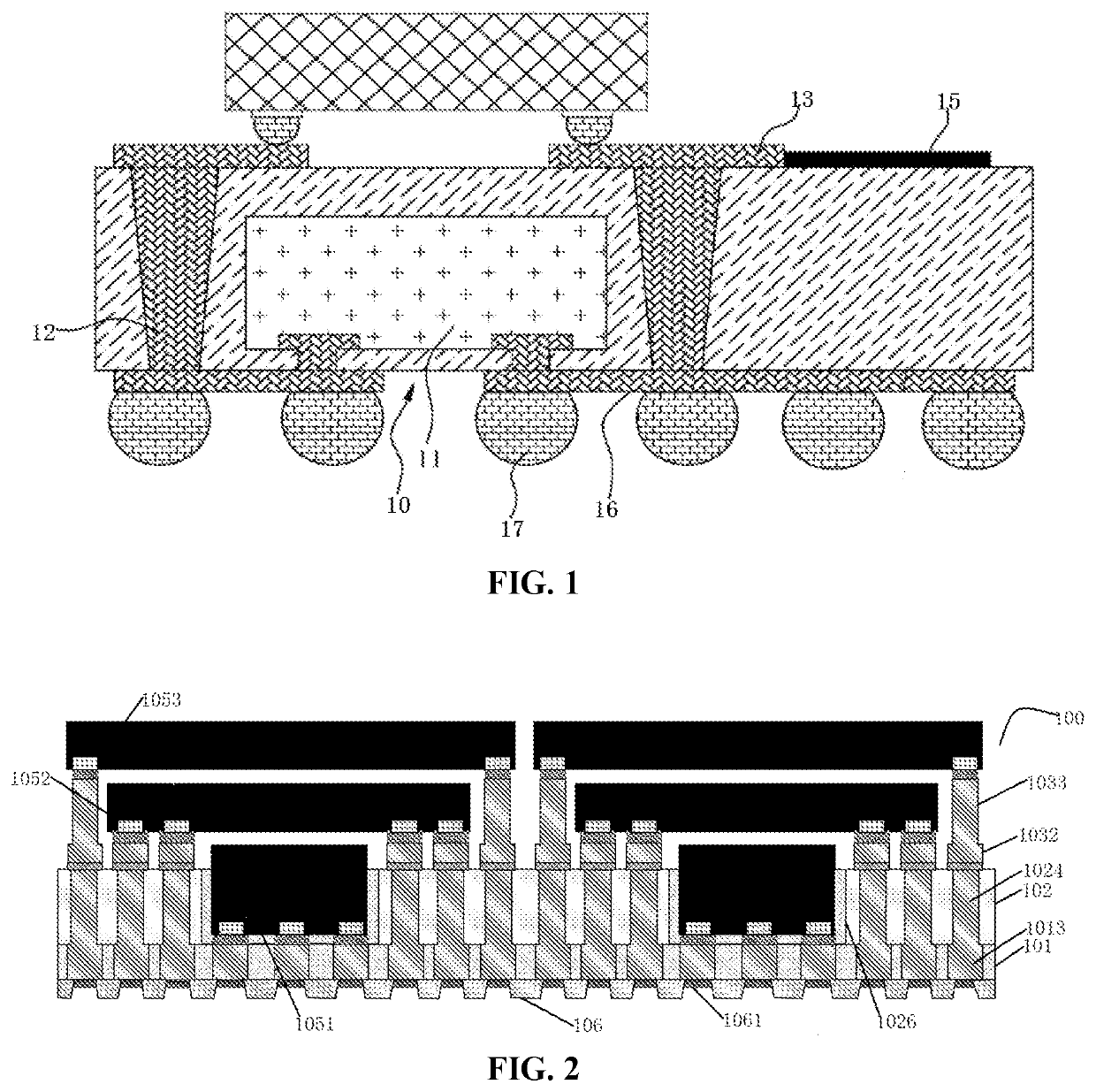
[0066]Referring to FIG. 2, a schematic cross-sectional view of an embedded packaging structure 100 is shown. The packaging structure 100 includes a first dielectric layer 101 and a second dielectric layer 102 on the first surface of the first dielectric layer 101. The first dielectric layer 101 and the second dielectric layer 102 may comprise the same material or different materials; and may comprise organic dielectric materials, inorganic dielectric materials or combinations thereof, preferably, polyimides, epoxy resins, bismaleimide triazine resins (BT), ceramic filler, glass fibers, or combinations thereof.

[0067]The first dielectric layer 101 comprises a first wiring layer 1013, the first wiring layer 1013 is exposed on the first surface of the first dielectric layer 101, the second dielectric layer 102 comprises a first through-hole pillar 1024 penetrating the second dielectric layer 102 in a height direction and a device placement port frame 1026, the second dielectric layer 10...


PUM

PropertyMeasurementUnit
thicknessaaaaaaaaaa
thicknessaaaaaaaaaa
thicknessaaaaaaaaaa

Abstract

A multilayer embedded packaging structure according to an embodiment includes a first dielectric layer and a second dielectric layer on the first dielectric layer. The first dielectric layer includes a first wiring layer. The second dielectric layer includes a first copper pillar layer and a device placement port frame penetrating through the second dielectric layer in a height direction, and a second wiring layer on the first copper pillar layer. A second copper pillar layer is on the second wiring layer. The first wiring layer and the second wiring layer are conductively connected via the first copper pillar layer. A first device is mounted to the bottom of the device placement port frame, a second device is mounted to the second dielectric layer, and a third device is mounted to an end of the second copper pillar layer.

Description

CROSS-REFERENCE TO RELATED APPLICATION(S)[0001]This application claims priority to Chinese patent application no. 202110294274.6 filed on Mar. 19, 2021 in the Chinese intellectual property office, the entire disclosure of which is incorporated by reference herein.BACKGROUND1. Technical Field[0002]The present invention relates to a packaging structure for an electronic device, and in particular to an embedded packaging structure and a manufacturing method thereof.2. Description of the Related Art[0003]With the rapid development of electronic technology, electronic products spring up, related electronic products go further and further on the road of intellectualization and integration, and the miniaturization and integration of related electronic products become the mainstream of the market. The miniaturization and intellectualization mean that each electronic component constituting the core part of the electronic products demands higher requirements, and how to manufacture lower cost...

Claims


Application Information

Patent Timeline
Patent Type & Authority Applications(United States)
IPC IPC(8): H01L23/538H01L25/10H01L25/065H01L23/31H01L23/29H01L21/48
CPCH01L23/5386H01L25/105H01L25/0652H01L23/3121H01L23/291H01L23/293H01L21/4857H01L21/486H01L24/16H01L23/3114H01L25/0657H01L21/56H01L2225/06517H01L2225/06524H01L2924/15313H01L2924/15156H01L2224/16235H01L2224/16238H01L21/6835H01L2221/68359H01L23/3128H01L23/5384H01L23/13H01L23/49811H01L2225/06513H01L2225/06555H01L2225/06568H01L25/03H01L2225/06582H01L21/4825H01L21/485H01L21/4853H01L21/52H01L2225/06548H01L2225/06527H01L23/49822H01L23/49838
Inventor CHEN, XIANMINGFENG, LEIHUANG, BENXIABAO, YUEWANG, WENSHI
Owner NANTONG ACCESS SEMICON CO LTD
Why Eureka
Try Eureka