
Porous Separator and Electrochemical Device Including the Same

a technology of porous separator and electrochemical device, which is applied in the manufacture of hybrid/edl cells, cell components, cell components, etc., can solve the problems of thermal runaway or perforation of separator, short-circuit between a positive electrode and a negative electrode, and surface coating defects, etc., to save cost, reduce weight, and small thickness

Pending Publication Date: 2022-10-06
LG ENERGY SOLUTION LTD
View PDF0 Cites 0 Cited by
  • Summary
  • Abstract
  • Description
  • Claims
  • Application Information

AI Technical Summary

Benefits of technology

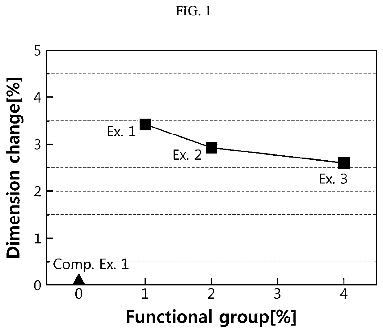
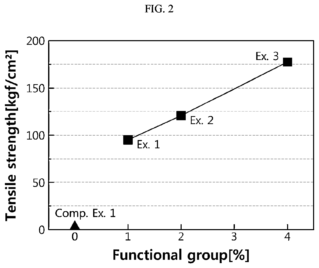
The present patent discloses a new kind of porous separator for batteries that is made without a polyolefin-based substrate, making it more cost-effective. The new separator has control over pore size and porosity, making it uniform. It is also thinner, which reduces weight and increases energy density. Additionally, it doesn't shrink when exposed to high temperatures, improving battery safety. Compared to existing separators, this new one has less dimensional change in electrolyte and improved strength and elongation.

Problems solved by technology

With regard to safety characteristics of electrochemical devices, there is great concern about explosion when an electrochemical device is overheated to cause thermal runaway or perforation of a separator.
Particularly, a polyolefin-based porous substrate used conventionally as a separator for an electrochemical device shows a severe heat shrinking behavior at a temperature of 100° C. or higher due to its material property and a characteristic during its manufacturing process, including orientation, thereby causing a short-circuit between a positive electrode and a negative electrode.
However, while forming the porous organic-inorganic coating layer, coating defects may be generated on the surface due to the cracking that occurs during a drying process, or the like.
For this reason, the coating layer may be detached with ease when a secondary battery is assembled or used, resulting in degradation of battery safety.
In addition, the slurry for forming a porous coating layer applied to the polyolefin-based porous substrate in order to form the coating layer may have a portion where particles are packed with higher density due to an increase in density of particles during drying to cause the problem of degradation of air permeability.
Further, when the porous coating layer is formed on a polyolefin substrate, there are problems in that the separator shows low adhesion to an electrode and has a relatively large thickness which does not meet a recent tendency of thin filming of a separator.

Method used


Image

  • Porous Separator and Electrochemical Device Including the Same
  • Porous Separator and Electrochemical Device Including the Same

Examples


example 2

[0103]A modified binder polymer including polyvinylidene fluoride (homo-PVdF) substituted with 2% of a carboxyl (COOH)-containing monomer, based on 100 wt % of the modified PVdF-based binder polymer, was prepared. Particularly, a porous separator and a lithium secondary battery were obtained in the same manner as Example 1, except that the modified PVdF-based binder polymer having a weight average molecular weight of 600,000 g / mol was used.

example 3

[0104]A modified binder polymer including polyvinylidene fluoride (homo-PVdF) substituted with 4% of a carboxyl (COOH)-containing monomer, based on 100 wt % of the modified PVdF-based binder polymer, was prepared. Particularly, a porous separator and a lithium secondary battery were obtained in the same manner as Example 1, except that the modified PVdF-based binder polymer having a weight average molecular weight of 600,000 g / mol was used.


PUM

PropertyMeasurementUnit
dielectric constantaaaaaaaaaa
melting pointaaaaaaaaaa

Abstract

Disclosed is a free-standing porous separator including a plurality of inorganic particles and a binder polymer positioned on the whole or a part of the surface of the inorganic particles to connect the inorganic particles with one another and fix them, wherein the binder polymer comprises a polyvinylidene fluoride (PVdF)-based binder polymer modified with an ester (COO)- or carboxyl (COOH)-containing monomer. An electrochemical device including the free-standing porous separator is also disclosed. It is possible to provide a porous separator which has a reduced dimensional change in an electrolyte, while showing improved tensile strength and / or elongation at the same time.

Description

TECHNICAL FIELD[0001]The present disclosure relates to a porous separator and an electrochemical device including the same. Particularly, the present disclosure relates to a porous separator having improved mechanical properties and inhibiting a dimensional change in an electrolyte, and an electrochemical device including the same.[0002]The present application claims priority to Korean Patent Application No. 10-2019-0097678 filed on Aug. 9, 2019 in the Republic of Korea, the disclosures of which are incorporated herein by reference.BACKGROUND ART[0003]Recently, energy storage technology has been given an increasing attention. Efforts into research and development for electrochemical devices have been actualized more and more, as the application of energy storage technology has been extended to energy for cellular phones, camcorders and notebook PC and even to energy for electric vehicles. In this context, electrochemical devices have been most spotlighted. Among such electrochemical...

Claims


Application Information

Patent Timeline
Patent Type & Authority Applications(United States)
IPC IPC(8): H01M50/446H01M50/406H01M50/426H01M50/431
CPCH01M50/446H01M50/406H01M50/426H01M50/431H01M50/417H01M50/403H01M10/052H01G11/52Y02E60/10H01G11/84H01M50/443H01M50/491H01M50/489H01M50/46
Inventor KIM, MIN-JILEE, SEUNG-HYUNJEONG, SO-MIHAN, DA-KYUNG
Owner LG ENERGY SOLUTION LTD
Learn More