Floating tunnel shore connecting system, floating tunnel, and floating tunnel construction method thereof

a technology of connecting system and floating tunnel, which is applied in the direction of bridges, artificial islands, bridges, etc., can solve the problems of weak horizontal rigidity of the scheme conceived for anchor-pull floating tunnel technology, affecting structural safety, driving safety and passengers' comfortable experience, and prone to elastic shock

Pending Publication Date: 2022-10-13
CHINA COMMUNICATIONS CONSTRUCTION
View PDF0 Cites 0 Cited by
  • Summary
  • Abstract
  • Description
  • Claims
  • Application Information

AI Technical Summary

Benefits of technology

[0016]A floating tunnel design method provided by the present invention, relative to the technical problem that the horizontal rigidity of existing pontoon type floating tunnel is weaker, and in the terms of the technical problems that the horizontal rigidity is still weaker relative to the scheme of the existing anchor-pull floating tunnel technical conception, and the slack and snap phenomenon is prone to occur, the horizontal stiffness and vertical stiffness of the entire tube body of the floating tunnel can be significantly increased by applying axial tension (the axial tension force is applied to the outside along the axial direction of the tube body) to the tube body at one end or both ends of the floating tunnel, which plays as an additional role in restraining the movement of the tube body, thereby increasing the natural vibration frequency of the floating tunnel body, avoiding the high-energy area of the wave spectrum, reducing the deflection and acceleration of the floating tunnel tube body, and increasing the design redundancy, which improves the safety and reliability of the floating tunnel. Due to the increase of the axial tension, the floating tunnel tube body becomes a structural system with high frequency natural vibration, such as a “string”, through a faster frequency vibration and combining with the surrounding water of the tube body, it can effectively play a damping effect. So that when the floating tunnel is moved by waves and currents, the high-frequency vibration of the tube body can make the energy consumption faster. This feature means that the total kinetic energy consumption of the structure for the anchor-pull floating tunnel can be more concentrated on the tube body, which can effectively reduce the stress variation on the cable anchored on the seabed or the riverbed, which is beneficial to the long-term use of the cable and the foundation anchored on the seabed or the riverbed. It can effectively save the construction cost and effectively reduce the maintenance difficulty.
[0090]5. The construction method of the floating tunnel of the present invention, by manufacturing the floating section of the floating tunnel, a joint section and a pull-stop section, by firstly connecting a joint section to the shore foundation by using a tension device, and at the same time connect the pull-stop section to the shore foundation. Then, after splicing them in sections to form the floating section, the floating section connects the joint section and the pull-stop section respectively to form the whole floating tunnel tube body. The construction method is simple to operate, can effectively reduce the stress variation of the cable anchored on the seabed or riverbed, is beneficial to the long-term use of the cable and the foundation anchored on the seabed or riverbed. The construction risk is lower and the cost is lower. It effectively saves the construction cost, effectively reduces the maintenance difficulty, and is easy to implement and popularize the project.

Problems solved by technology

The scheme conceived for buoy floating tunnel technology has the problem that the horizontal rigidity is still weak, which affects the structural safety, driving safety and passengers' comfortable experience.
The horizontal rigidity of the scheme conceived for anchor-pull floating tunnel technology is still weak, and it is also prone to the phenomenon of elastic shock.
Two kinds of floating tunnel structures are easy to high risk of transmitting resonance when meet the natural wave high-energy area, which seriously affects the above-mentioned shortcomings of the safety of the floating tunnel.

Method used


Image

  • Floating tunnel shore connecting system, floating tunnel, and floating tunnel construction method thereof
  • Floating tunnel shore connecting system, floating tunnel, and floating tunnel construction method thereof
  • Floating tunnel shore connecting system, floating tunnel, and floating tunnel construction method thereof

Examples


embodiment 1

[0107]The present embodiment 1 provides a design method for a floating tunnel, wherein axial tension is applied respectively along both ends of the tube body 1 of the floating tunnel. Of course, an axial tensile force can also be applied along one end of the tubular body 1 of the floating tunnel, while the other end only provides a reaction force.

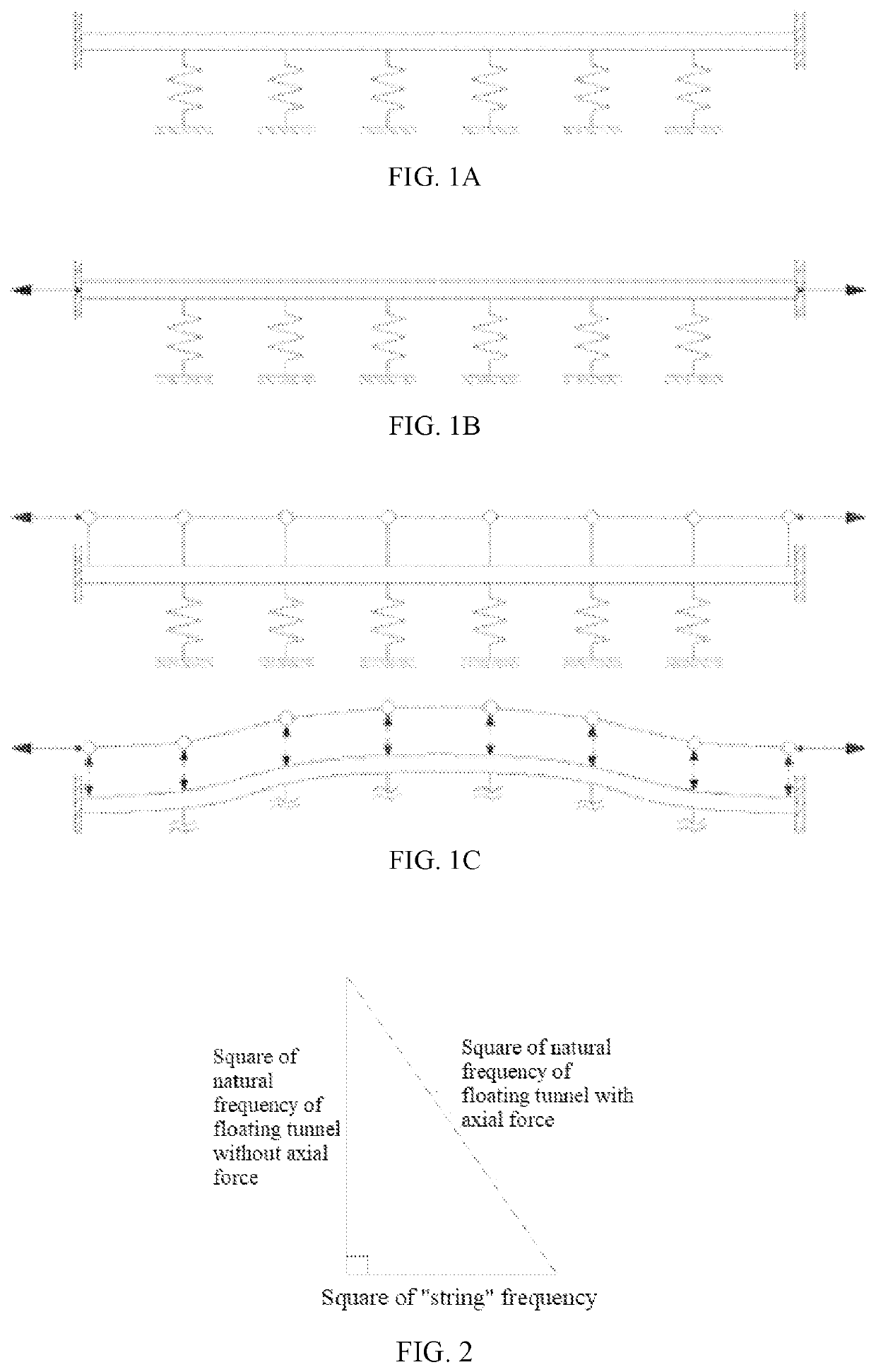
[0108]By analyzing the force of the floating tunnel tube body 1, the changes in the front and rear forces when axial tension is applied at both ends of the floating tunnel tube body 1. As shown in FIGS. 1a-1c, the structural stiffness system of the floating tunnel in the prior art is composed of the stiffness contribution of the tube body 1 and the anchor system (as shown in FIG. 1a), and the anchor system can be a cable 22 or a ponton, or can also be a combination of the two. In this embodiment, by applying the axial tension of the tube body 1 (shown in FIG. 1b), it additionally increases the stiffness (see FIG. 1c for the principle), ther...

embodiment 2

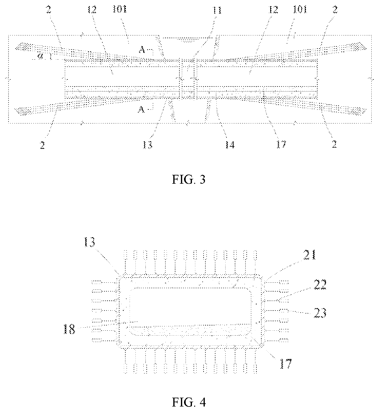
[0125]As shown in FIG. 3-5, Embodiment 2 also provides a floating tunnel shore connecting system, which includes a joint section 12 located at the end of the floating tunnel, which can move axially along the tube body. The joint section 12 is provided with a tension device 2, which is used to apply axial tension to the joint section 12.

[0126]Wherein, the above-mentioned joint section 12 passes through the shore foundation 101, but is not fixed or hinged connected to the shore foundation 101. The joint section 12 can move along the axial direction of the tube body 1 relative to the shore foundation 101, so as to avoid the reaction force provided by the shore foundation 101 to the joint section 12 when the joint section 12 is pulled by the tension device 2 to reduce the influence of the horizontal rigidity of the tension device lifting the tube body 1.

[0127]The tension device 2 is connected to the shore foundation 101, and by directly connecting the tension device 2 to the shore found...

embodiment 3

[0134]As shown in FIG. 3-5, Embodiment 3 provides a floating tunnel, which includes a tube body 1 and a hollow cavity 18. The tube body 1 includes a floating section 11, and both ends of the floating section 11 are respectively connected with the shore connecting system as in Embodiment 2 above; The joint sections 12 all pass through the shore foundation 101, and the two joint sections 12 are provided with tension devices 2, which are used to apply axial tension to the corresponding joint sections 12.

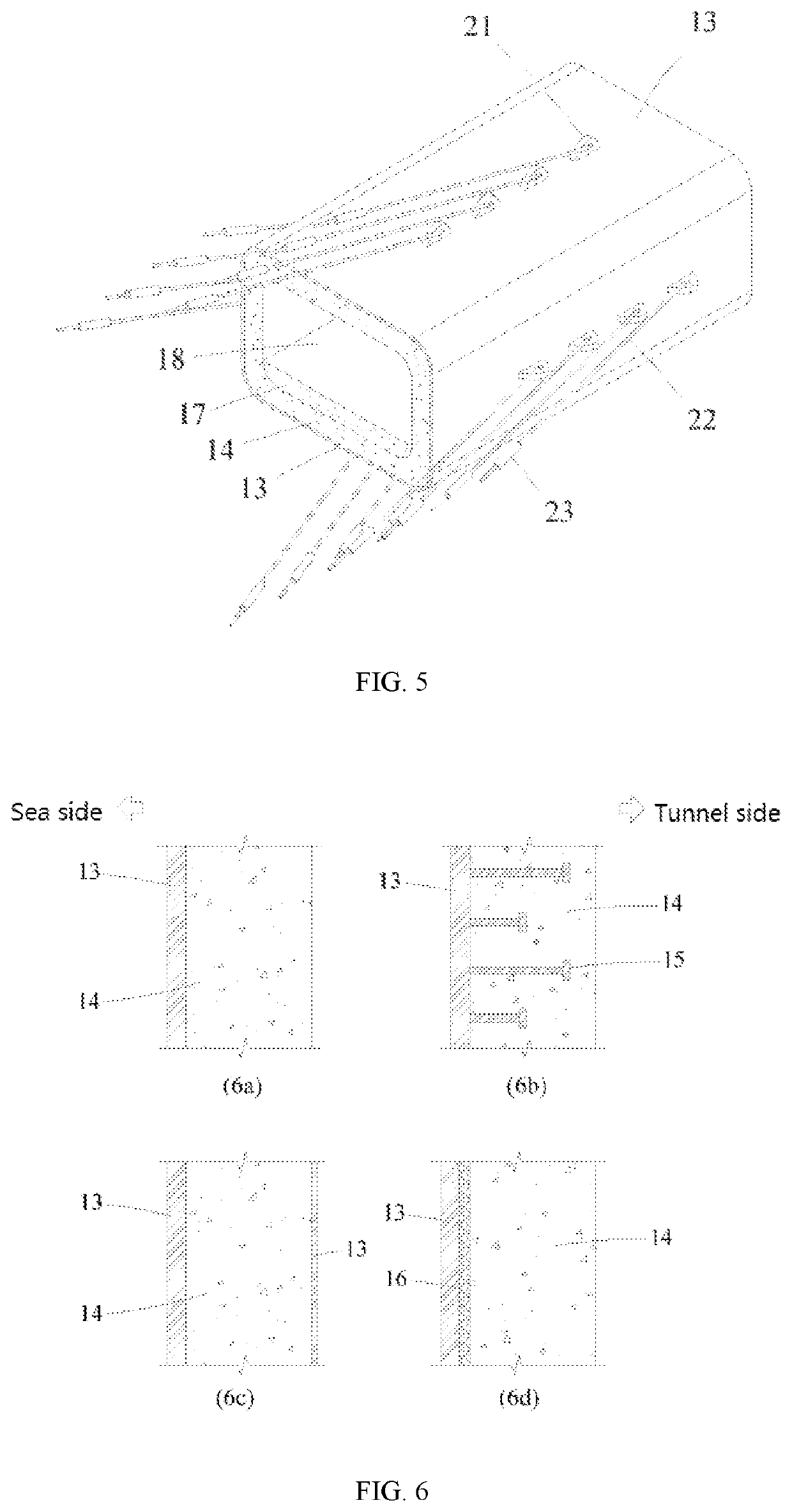
[0135]Wherein, the sizes of the above-mentioned two axial tensions are the same, and the directions of the axial tensions are opposite. The floating section 11 and the two joint sections 12 both include a steel plate layer 13 and a reinforced concrete layer 14 located in the steel plate layer 13, all the steel plate layers 13 are integral structural members, and all the reinforced concrete layers 14 are integral structural members. The cross-sectional shape of the tube body 1 is round (...


PUM


Abstract

A floating tunnel shore connecting system, a floating tunnel and a floating tunnel construction method are disclosed, where the design method of the floating tunnel is to apply axial tension along one end or two ends of a tube body respectively; The floating tunnel shore connecting system comprises a joint section located at the end of the tube body, which can move along the axial direction and is connected with a tension device for applying axial tension; The floating tunnel comprises a tube body and a hollow cavity, wherein the tube body comprises a floating section and a shore connecting system at two ends, and both joint sections are provided with tension devices. The design method and structure of the floating tunnel provided by the present invention, by applying the axial tension of the tube body, can significantly increase the horizontal stiffness and vertical stiffness of the whole floating tunnel tube body, improving the natural vibration frequency of the tube body, and the safety and reliability of the floating tunnel are improved; It is beneficial to the long-term use of the cable and the foundation anchored on the seabed or the riverbed. The construction risk is also lower, and the cost is also lower, which effectively saves the construction cost, and is easy to implement and popularize the project.

Description

RELATED APPLICATIONS[0001]The present application is a continuation of International Appl. No. PCT / CN2020 / 129975, filed Nov. 19, 2020, pending, which claims priority to Chinese Pat. Appl. No. 201911135735.4, filed Nov. 19, 2019, both of which are incorporated herein by reference in their entireties.FIELD OF THE INVENTION[0002]The present invention relates to the technical field of floating tunnel engineering, particularly a floating tunnel shore connecting system, a floating tunnel thereof, and a floating tunnel construction method.Background Technical[0003]As a new type of traffic mode across the water area, the floating tunnel in water generally through the combined action of the self-weight and buoyancy of the structure and the anchoring system set on the underwater foundation to maintain the balance and stability of the floating tunnel in water. Because of the complex structure and working environment of the floating tunnel, there is no successful precedent in the world at prese...

Claims


Application Information

Patent Timeline
Patent Type & Authority Applications(United States)
IPC IPC(8): E02D29/067E01D15/14
CPCE02D29/067E01D15/14E02D2600/30E02D2250/00
Inventor LIN, WEITIAN, YINGHUIYIN, HAIQING
Owner CHINA COMMUNICATIONS CONSTRUCTION
Why Eureka
Try Eureka