Flameless combustor

a combustor and flameless technology, applied in the field of flameless combustor, can solve the problems of limited oxidation rate of mixing upon mixing, low permeability formation not amiable to enhanced oil recovery methods, and time-consuming process for starting the heater of patent '742

Inactive Publication Date: 2000-02-01
SHELL OIL CO
View PDF24 Cites 372 Cited by
  • Summary
  • Abstract
  • Description
  • Claims
  • Application Information

AI Technical Summary

Problems solved by technology

Formations of low permeability are not amiable to enhanced oil recovery methods such as steam, carbon dioxide, or fire flooding.
Further, start-up of the heater of patent '742 is a time consuming process because it must operate at temperatures above the autoignition temperature of the fuel gas mixture.
Generally, flameless combustion is accomplished by preheating combustion air and fuel gas sufficiently that when the two streams are combined the temperature of the mixture exceeds the autoignition temperature of the mixture, but to a temperature less than that which would result in the oxidation upon mixing being limited by the rate of mixing.
Preheating of the streams to a temperature between about 1500.degree. F. and about 2300.degree. F. and then mixing the fuel gas into the combustion a...

Method used


Image

  • Flameless combustor
  • Flameless combustor

Examples


Embodiment Construction

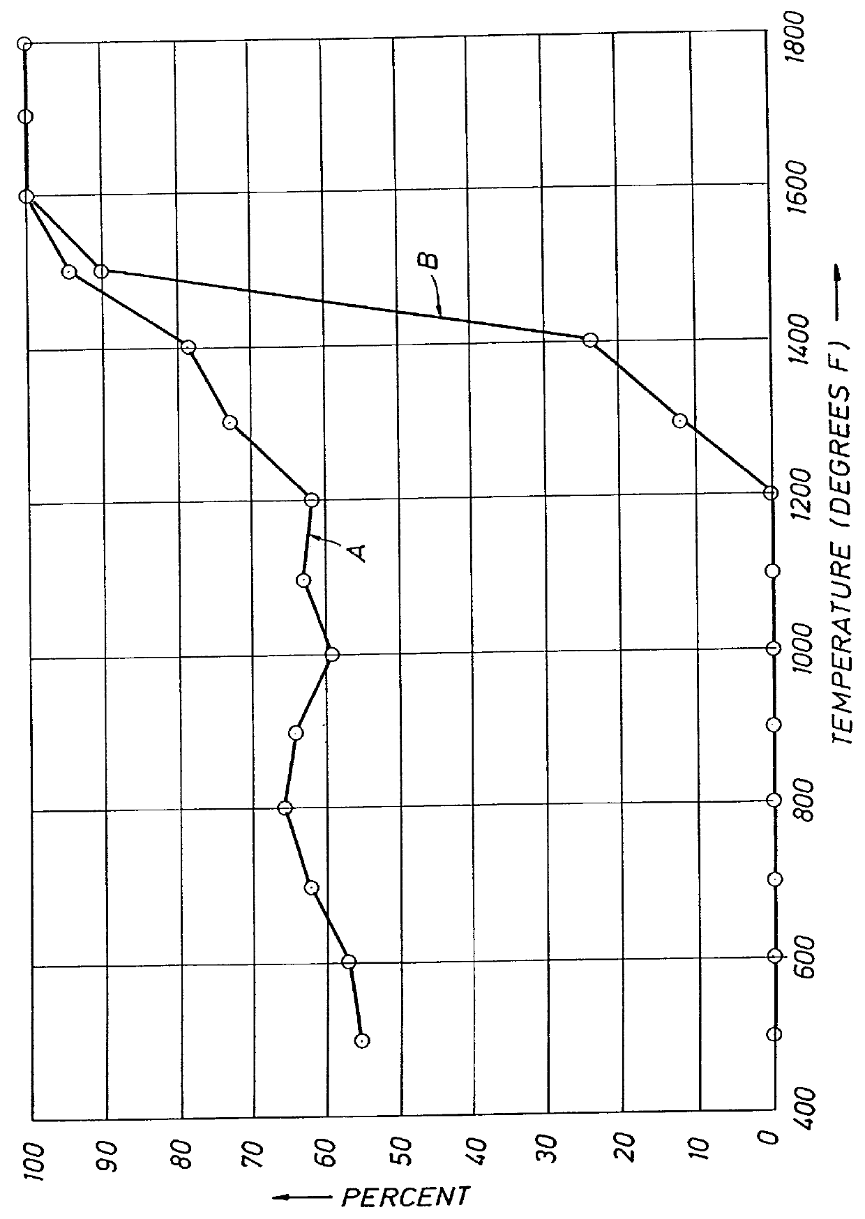
A thermal reactor was used to establish temperatures at which oxidation reactions would occur with various combinations of fuels, oxidants and catalyst surfaces. The reactor was a one inch stainless steel pipe wrapped with an electrical resistance heating coil, and covered with insulation. A thermocouple for temperature control was placed underneath the insulation adjacent to the outer surface of the pipe. Thermocouples were also provided inside the pipe at the inlet, at the middle, and at the outlet. Test ribbons of noble metals or stainless steel strips with noble metal coatings were hung in the pipe to test catalytic activity. Air preheated to a temperature somewhat below the desired temperature of the test was injected into the electrically heated test section of the pipe. Electrical power to the electrical resistance heater was varied until the desired temperature in the test section was obtained and a steady state, as measured by the thermocouples mounted inside the pipe, was ...


PUM


Abstract

A combustor method and apparatus is provided. The method utilizes flameless combustion with one or more of three improvements to enhance ignition of the flameless combustor. A catalytic surface can be provided within a combustion chamber to provide flameless combustion at least in the vicinity of the catalytic surface at a temperature that is much lower than the autoignition temperature of fuel in air without the presence of the catalytic surface. Nitrous oxide or supplemental oxygen may also be used as an oxidant either instead of air or with air to reduce ignition temperatures. Further, electrical energy can be passed through the fuel conduit, raising the temperature of the conduit to a temperature above which the fuel will ignite when combined with the oxidant.

Description

This invention relates to a combustor apparatus and method.BACKGROUND TO THE INVENTIONU.S. Pat. Nos. 4,640,352 and 4,886,118 disclose conductive heating of subterranean formations of low permeability that contain oil to recover oil therefrom. Low permeability formations include diatomites, lipid coals, tar sands, and oil shales. Formations of low permeability are not amiable to enhanced oil recovery methods such as steam, carbon dioxide, or fire flooding. Flooding materials tend to penetrate formations that have low permeabilities preferentially through fractures. The injected materials bypass most of the formation hydrocarbons. In contrast, conductive heating does not require fluid transport into the formation. Oil within the formation is therefore not bypassed as in a flooding process. When the temperature of a formation is increased by conductive heating, vertical temperature profiles will tend to be relatively uniform because formations generally have relatively uniform thermal ...

Claims


Application Information

Patent Timeline
IPC IPC(8): A47G25/00A47G25/90E21B36/02E21B43/16E21B36/00E21B43/243
CPCE21B36/02E21B43/243F23C13/02F23C2900/99001Y02E20/342Y02E20/34
Inventor WELLINGTON, SCOTT LEEMIKUS, THOMASVINEGAR, HAROLD J.KARANIKAS, JOHN MICHAEL
Owner SHELL OIL CO
Why Eureka
Try Eureka