Direct conversion receiver with reduced even order distortion

Inactive Publication Date: 2000-02-01
TELEDYNE SCI & IMAGING
View PDF13 Cites 43 Cited by
  • Summary
  • Abstract
  • Description
  • Claims
  • Application Information

AI Technical Summary

Benefits of technology

The present invention relates to a direct conversion receiver optimized to reduce even order distortion. The direct conversion receiver includes a signal input, an oscillator input, an output, a distortion compensation circuit and a mixing circuit. The distortion compensation circuit is coupled to the output. The distortion com

Problems solved by technology

Direct conversion receivers often have a performance limitation related to even order distortion.
For example, in high-performance receiver applications, standards require that a strong off-channel signal cannot mask a weak on-channel signal.
This requirement can cause pr

Method used


Image

  • Direct conversion receiver with reduced even order distortion
  • Direct conversion receiver with reduced even order distortion
  • Direct conversion receiver with reduced even order distortion

Examples


Embodiment Construction

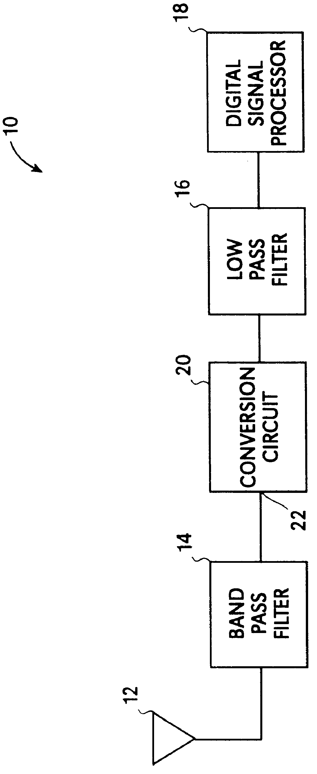
In FIG. 1, a direct conversion receiver (DCR) system 10 includes an antenna 12, a band-pass filter 14, a mixer or conversion circuit 20, a low-pass filter 16, and a digital signal processor 18. Radio frequency (RF) signals are received on antenna 12 and provided through a band-pass filter 14 to an input 22 of circuit 20. The RF signals are preferably modulated high frequency signals and can be ultra-high frequency (UHF), very-high frequency (VHF), or other frequency signals.

System 10 can be utilized in a variety of communication applications, including aircraft radio receivers. Circuit 20 utilizes an oscillator signal to convert the RF signal at input 22. The oscillator signal can be produced by any frequency source, such as, a voltage controlled oscillator, a direct digital synthesizer, a divider or other high frequency signal source. The oscillator signal can be in the UHF, VHF or other frequency range.

Circuit 20 provides a mixed or composite signal comprised of the local oscillat...


PUM


Abstract

A mixer for use in a direct conversion receiver includes a compensating differential amplifier which injects equal amplitude opposite phase currents with respect to even order distortion currents. The compensating differential amplifier utilizes an ideal current source. The mixer is an active mixer which utilizes four switching transistors. The even order distortion is introduced by non-linear components which demonstrate strong off-channel signals.

Description

The present invention relates to a higher frequency circuit including an even order distortion cancellation circuit. More particularly, the present invention relates to a direct conversion receiver (DCR) having reduced even order distortion.BACKGROUND OF INVENTIONIn communication applications, a direct conversion receiver (DCR) can be utilized to convert a modulated radio frequency (RF) signal to the original frequency or baseband frequency in a single step. Typically, the modulated RF signal undergoes a single frequency conversion to a "zero" intermediate frequency (IF) signal. The zero IF signal contains the modulated information.Generally, a mixer is employed to generate the zero IF signal by mixing a local oscillator (LO) signal which is equal to the center or carrier frequency of the modulated RF signal. The mixed or zero IF signal contains the baseband frequency as well as the local oscillator frequency, the carrier frequency and the local oscillator frequency plus the carrier...

Claims


Application Information

Patent Timeline
IPC IPC(8): H03D7/14H04B1/10H04B1/30H04B1/18
CPCH03D7/1433H04B1/109H03D7/1408H03D7/1441H03D7/1458H04B1/18H04B1/30H03D2200/0033H03D2200/0088
Inventor VAGHER, MICHAEL R.
Owner TELEDYNE SCI & IMAGING
Why Eureka
Try Eureka