Valve timing adjusting apparatus for internal combustion engines

a timing adjustment and internal combustion engine technology, applied in the direction of valve drives, couplings, machines/engines, etc., can solve the problems of damage to the knock pin and the knock pin member, and it is difficult to improve the response characteristic of the phase control of the camshaft with respect to the timing pulley

Inactive Publication Date: 2000-02-15
DENSO CORP
View PDF14 Cites 41 Cited by
  • Summary
  • Abstract
  • Description
  • Claims
  • Application Information

AI Technical Summary

Benefits of technology

It is another object of the present invention to provide a valve timing adjusting apparatus that can be manufactured with ease.
Also desirable is the fact that, by providing a second mode for rotating the vane member to the one of the circumferential direction ends, phase control in both directions toward a leading angle side and a lagging angle side of the vane member relative to the housing member can be carried out with a high degree of accuracy.

Problems solved by technology

As a result, a force generated by the rotation of the internal rotor may be applied to the knock pin, causing a damage to the knock pin and members around the knock pin.
As a result, it is often difficult to improve the response characteristic of phase control of the camshaft with respect to the timing pulley.

Method used


Image

  • Valve timing adjusting apparatus for internal combustion engines
  • Valve timing adjusting apparatus for internal combustion engines
  • Valve timing adjusting apparatus for internal combustion engines

Examples


first embodiment

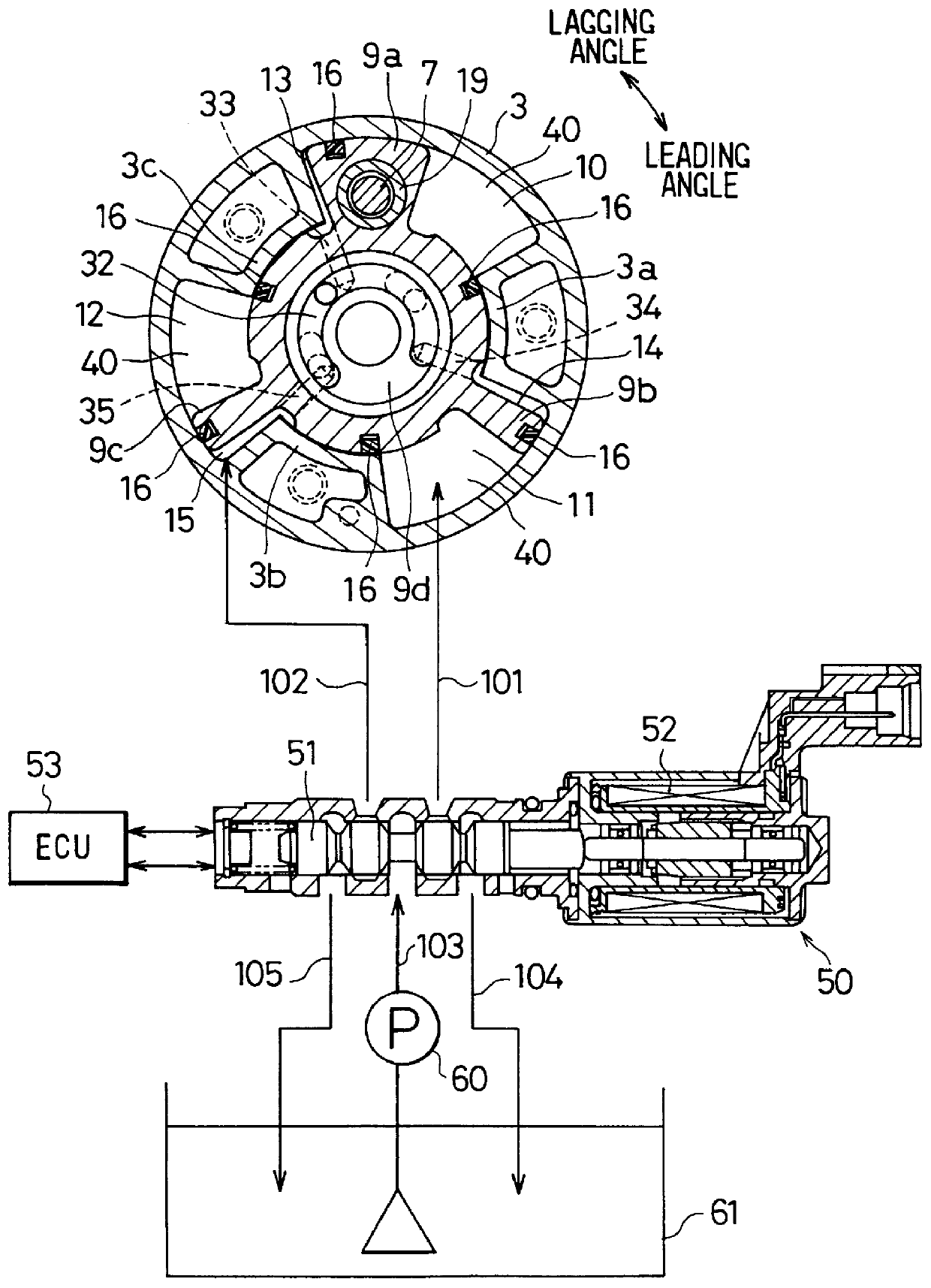
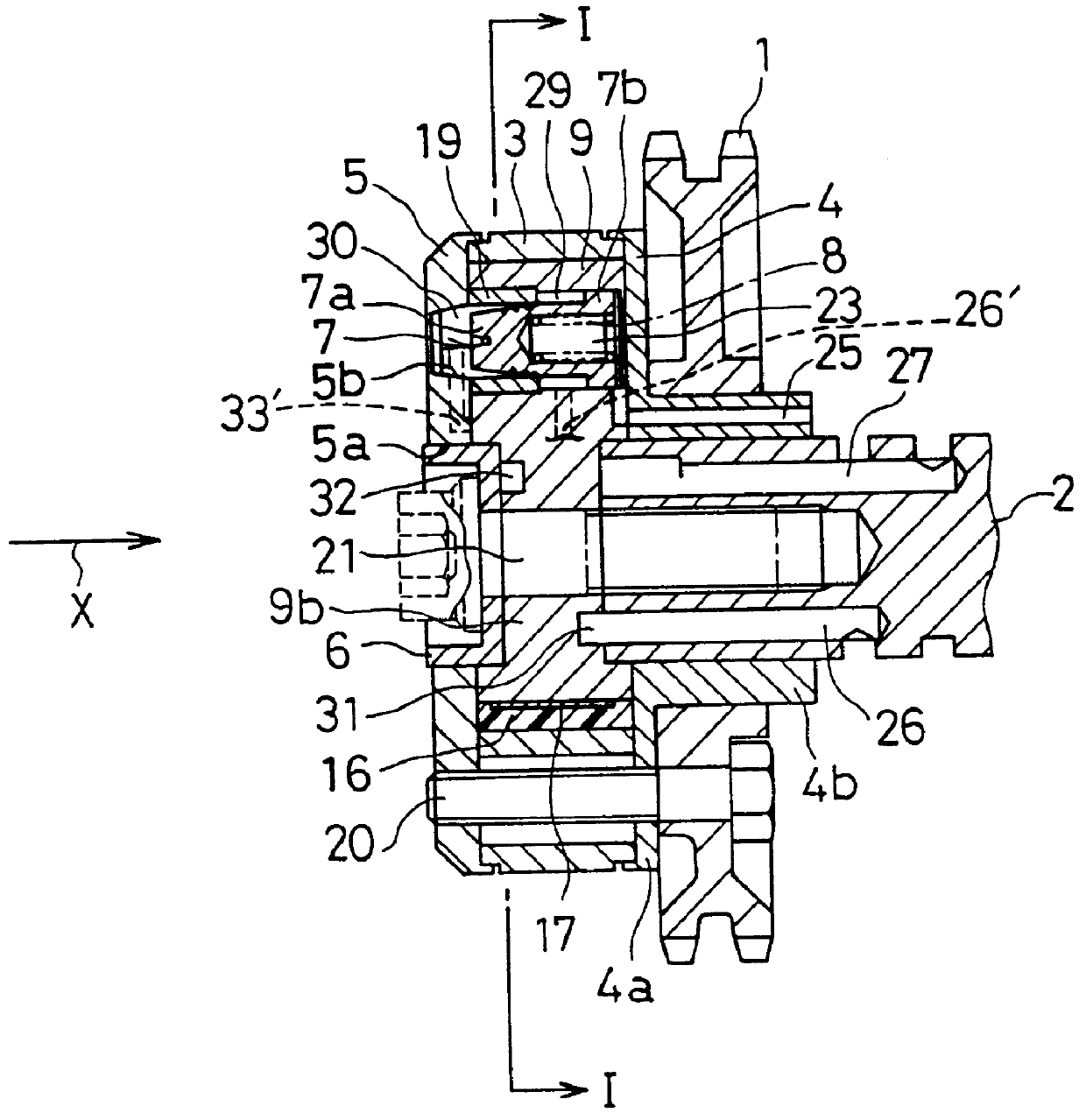
The positions of the stopper piston 7 and the stopper hole 5b are set so that, when the vane rotor 9 is located at a most lagging angular position with respect to the shoe housing 3, that is, when the camshaft 2 is rotated to a most lagging angular position with respect to the crank shaft, the stopper piston 7 can be fit in the stopper hole 5b by the energization force generated by the spring 8. In the first embodiment, the most lagging position is referred to as `one of two circumferential direction ends of an accommodation chamber`. On the other hand, a most leading position is referred to as `the other circumferential direction end of an accommodation chamber`.

Since a link path 25 formed on the cylindrical portion 4b is connected to an accommodation bore 23 on the rear member side rather than the flange 7b and also exposed to the atmosphere, the movement of the stopper piston 7 is not obstructed.

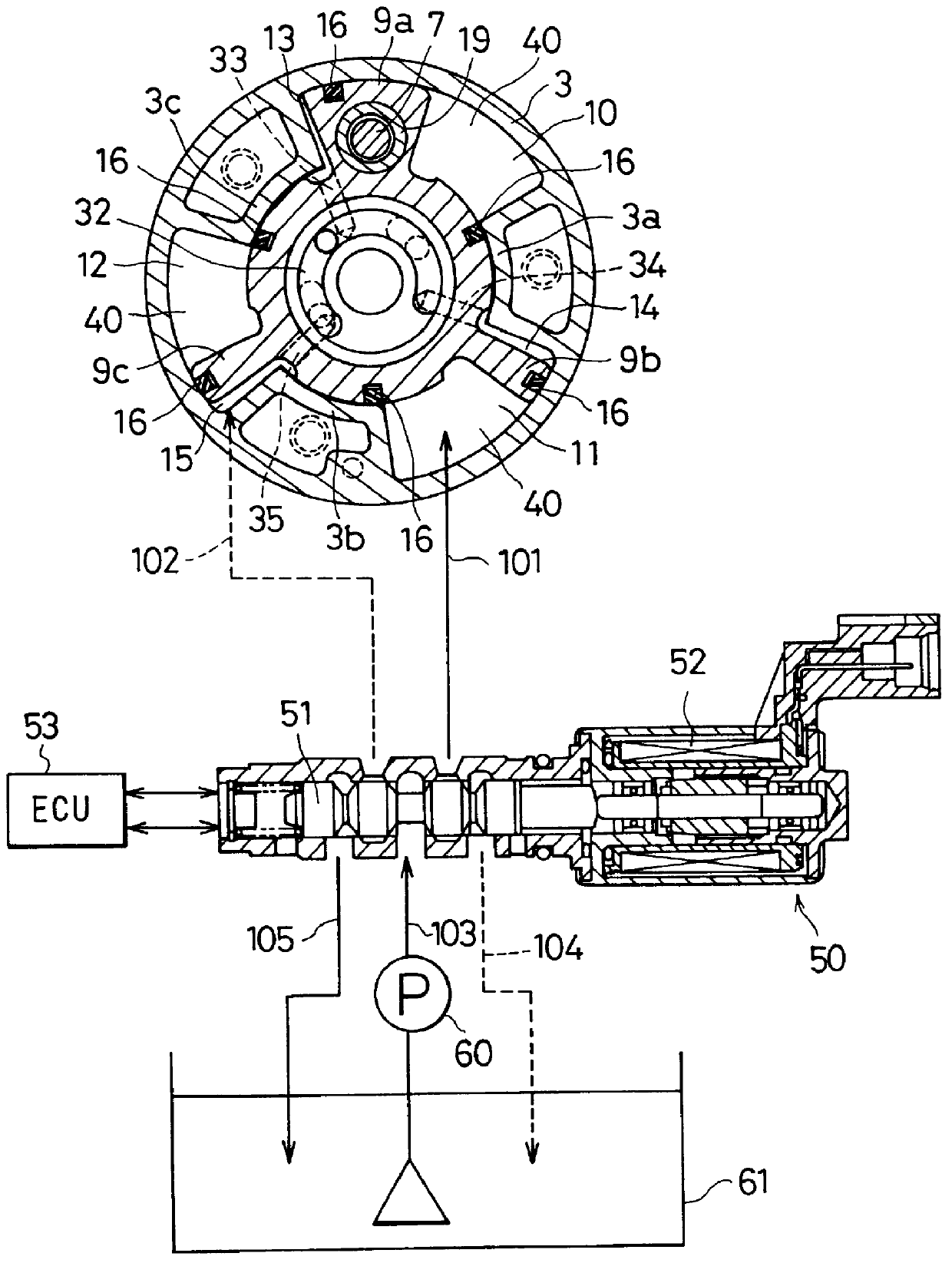
As shown in FIG. 1, lagging angle oil pressure chambers 10-12 are formed between the ...

second embodiment

(SECOND EMBODIMENT)

A second embodiment of the present invention is shown in FIGS. 7 and 8. Components virtually identical with those employed in the first embodiment are denoted by the same reference numerals as the latter.

A stopper piston 70 employed in the second embodiment is formed to have an almost uniform external radius along the axial direction thereof and supported by a guide ring 71 so that the stopper piston 70 can be moved back and forth. Oil pressure from only the oil pressure chamber 30 is applied to the stopper piston 70 to pull out the stopper piston 70 from the stopper hole 5b,and to overcome the force of a spring 72. For this reason, the area of an oil pressure receiving surface for receiving the oil pressure from the oil pressure chamber 30 can be made larger than that of the stopper piston 7 employed in the first embodiment.

Also in the case of the second embodiment, the phase control of the vane rotor 9 relative to the shoe housing 3 is carried out by using the c...


PUM


Abstract

A valve timing adjusting apparatus that selectively controls a restraint mechanism for restraining relative rotation between a housing member and a vane member to increase the operational life thereof. When a vane rotor is held at a most lagging angular position, an end holding mode is executed to pull out a stopper piston from a stopper hole by fluid pressures of both a leading angle side and a lagging angle side. As a result, when the vane rotor rotates from the most lagging angular position to the leading angle side, torsional forces on the stopper piston and the stopper hole can be minimized as the vane member direction of rotation changes. Since a fluid pressure has already been applied to each of leading angle fluid pressure chambers in the end holding mode, the vane rotor can be rotated from the most lagging angular position to the leading angle side quickly by increasing fluid pressure applied to each of the leading angle fluid pressure chambers without the need to switch a fluid path. In addition, since the fluid pressure applied to each of the leading angle fluid pressure chambers in the end holding mode is smaller than fluid pressure for rotating the vane rotor to the leading angle side, generation of impact sound due to collisions of vanes can be avoided.

Description

This application is related to and claims priority from Japanese Patent Application No. Hei 9-18826 filed on Jan. 31, 1997, the contents of which are hereby incorporated by reference.1. Field of the InventionThe present invention relates to a valve timing adjusting apparatus for changing opening / closing timing (referred to hereafter simply as valve timing) of at least one of an intake valve and an exhaust valve of an internal combustion engine (referred to hereafter simply as an engine).2. Description of Related ArtA vane type valve timing adjusting apparatus for controlling the valve timing of at least one of an intake valve and an exhaust valve is well known. Typically, the apparatus operates by driving a camshaft through a timing pulley or a chain sprocket rotating in synchronization with a crank shaft of the engine in accordance with a difference in phase between the camshaft and the timing pulley or the chain sprocket. Such an apparatus is disclosed in Japanese Patent Laid-open...

Claims


Application Information

Patent Timeline
Patent Type & Authority Patents(United States)
IPC IPC(8): F01L1/344F01L1/34
CPCF01L1/3442Y10T74/2102F01L2201/00
Inventor ADACHI, MICHIOUEDA, KENJI
Owner DENSO CORP
Why Eureka
Try Eureka